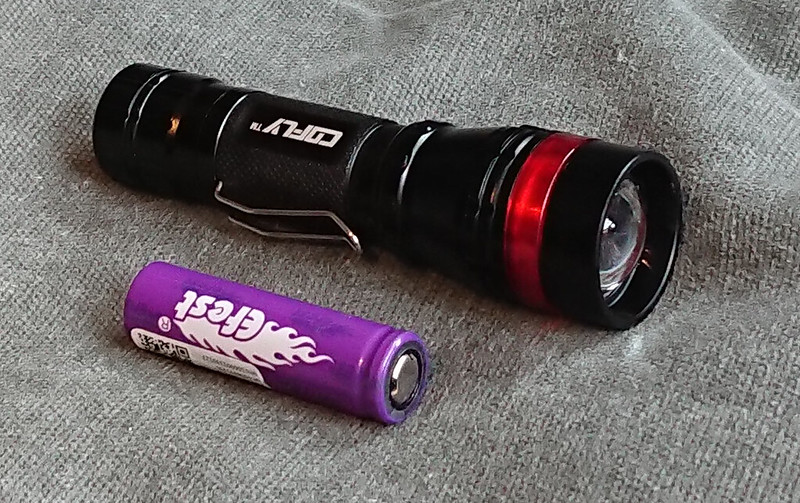
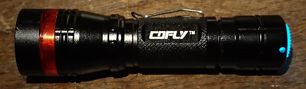
Pilotdog68 showed by starting the " what did you mod today" thread almost 3 years ago that modding was not dead on BLF but very much alive. That thread made me post more mods than I did before because a whole new thread was not needed now, many mods were not worth more than a quick post with one or a few pics and this thread is perfect for that. But since then I also do not post many comprehensive mod threads anymore, the WDYMT thread made me a bit lazy. So to compensate somewhat for that here's a very complete mod thread once more. I chose a cheap under 10 dollar zoomie that unfortunately is not for sale anymore, unfortunately because the build quality is not bad and it has a nice 21mm diameter (plastic) lens that makes for some decent throw considering the small size of the flashlight.
In this post I show many ways-methods-gear-parts that I picked up on BLF or developed myself, but in no way what I do here is how it should be done, there's many ways to do stuff and other modders have their own methods and specialities. But perhaps it does help people to see how someone else does things.
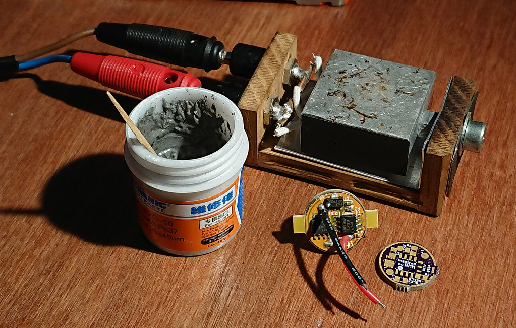
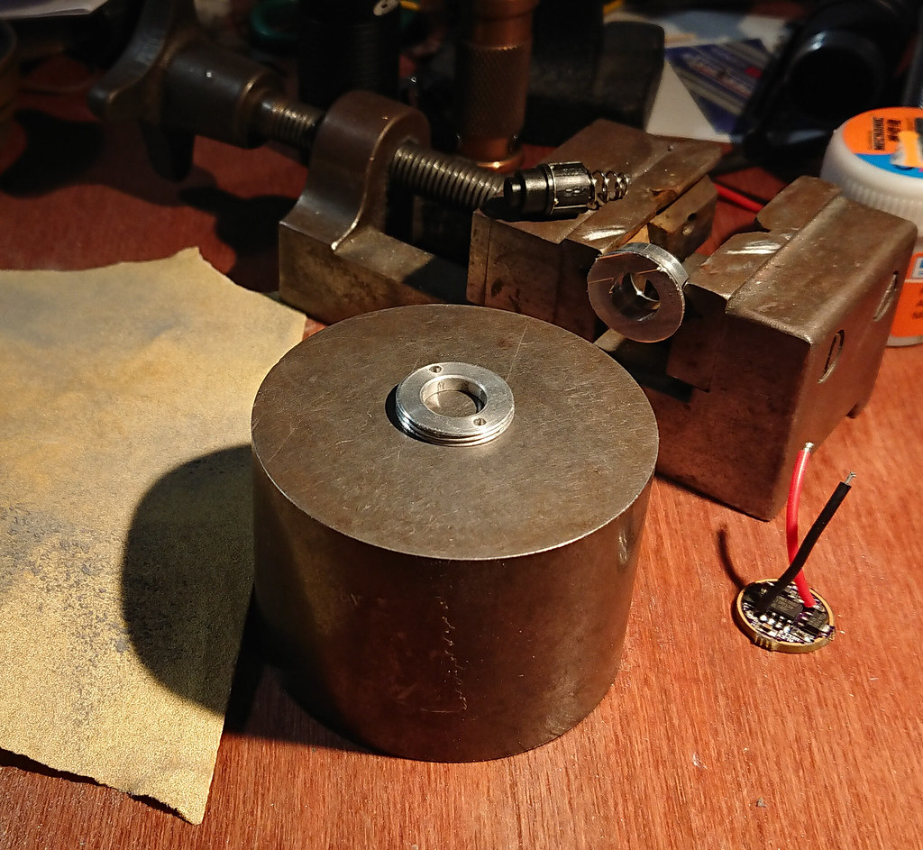
Apart from the specific materials used for this mod and can be seen in the pictures of the mod, here's some stuff that I use all the time:
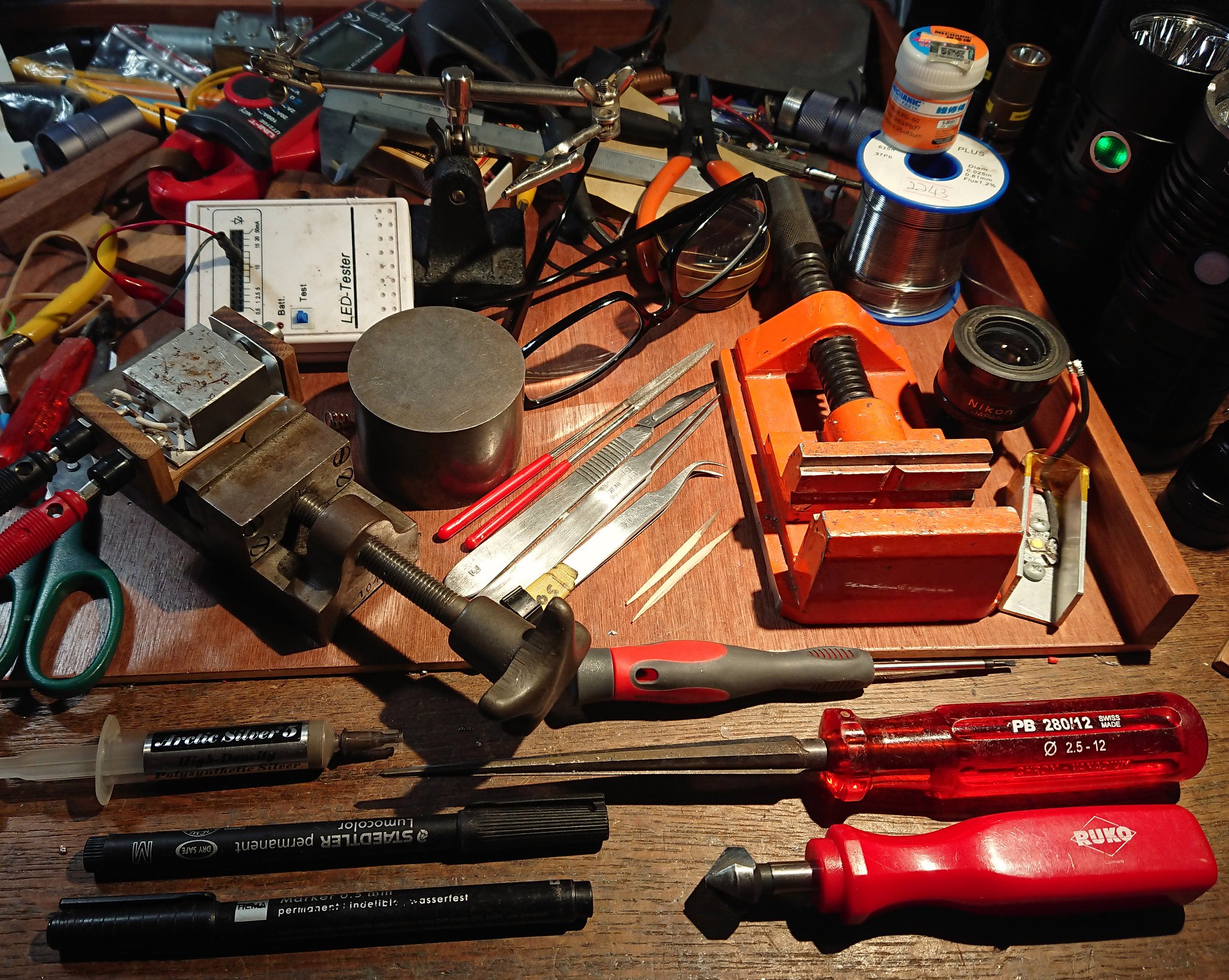
Some of the things in the photo: reamer, metal-grade countersink tool, heat block, round iron block with very flat upper surface (used as sanding base to flatten things), diamond files, tweezers, toothpicks, aluminium vice (alu=nice&grippy), test XM-L2, Nikon eyepiece used as a loupe, 63/37 rosin core solder wire, 63/37 solder paste, small cutting pliers, piece of a projection lens (=used in front of phonecamera to make macro-pictures), +4 reading glasses for close-up work, helping hands for soldering, led tester modded with clicky switch (instead of stock momentary switch), clamp meter, calliper.
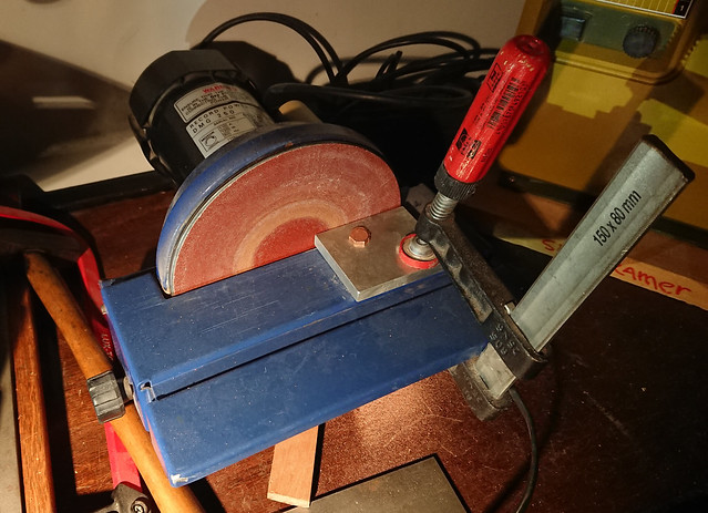
Not in picture: 25W Antex solder iron, 80W Antex solder iron, several power suppplies, disc sander, small model band saw, small drill press, numerous drawer storage cabinets with bits and parts, cardboard boxes, and more stuff among which a couple of flashlights 
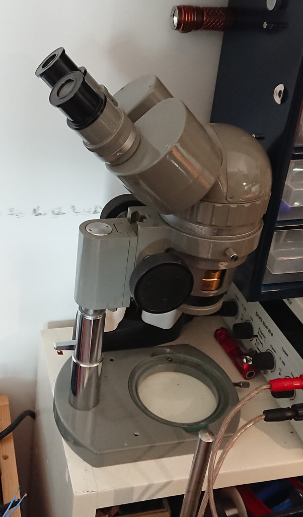
Oh, and I forgot this very often used thing, my 20x-80x Olympus zooming stereo microscope. To check things, to work through for tiny mods, and for making very detailed macro-pictures.
The mod.
I have several copies of this Cofly zoomie, and thusfar the best one has a dedomed XP-G2 S3 3D and a BLF X5/X6 bistro driver. I re-measured the light (@30 seconds with purple Efest14500) and it produces 54 kcd (same as the famous Jacob A60  ). With the new Osram "White Flat" 1mm-die thrower led I hope to make a version that throws even better :-)
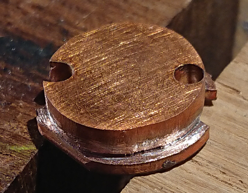
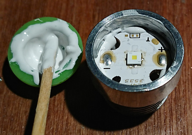
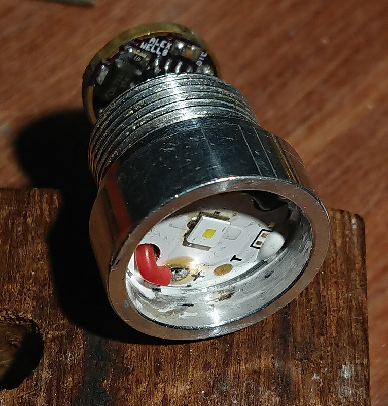
This zoomie has a hollow pill and although normally when using a copper DTP-board that is no problem for the heat path, with this led at close to 5 amps some extra measures are needed, I decided on a little chunk of copper under the ledboard.
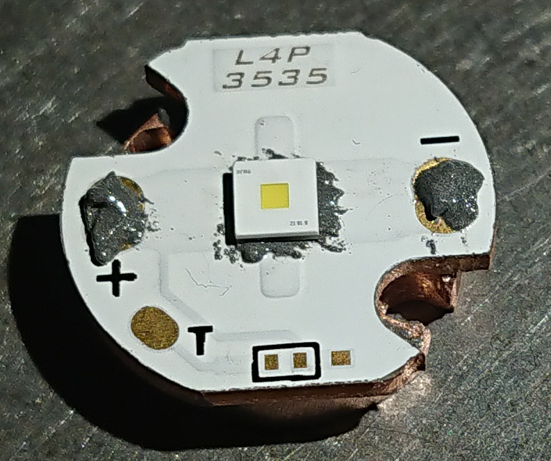
The ledboard
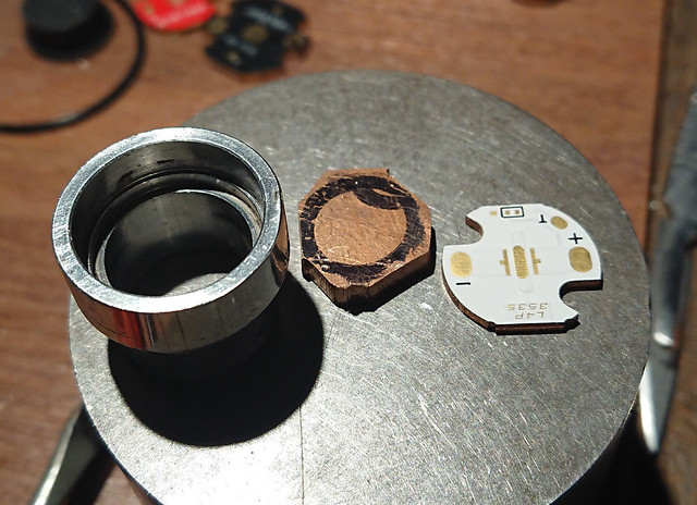
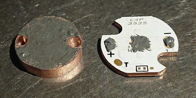
After sanding with disc sander and by hand with sand paper, and driling holes for the led wires:
Solder paste was added (yes, I use too much solder paste for the led!)
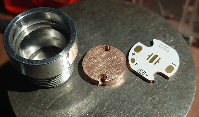
stacked
the stack was soldered together on my heat block, making sure that the copper chunk was centered well under the ledboard (info on the heat block here: https://budgetlightforum.com/t/-/44420 )

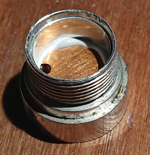
Excess solder on the underside was sanded and filed away
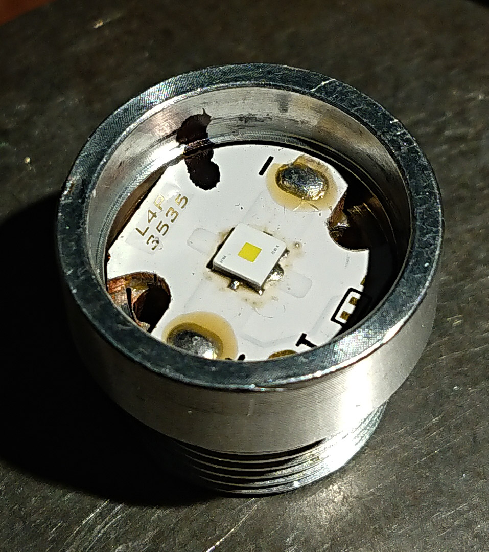
The assembly fitted tightly in the pill, but only in one orientation (pill=not perfectly round apparently ) I marked the working orientation with a sharpie.
the pill was loaded with Arctic Alumina Adhesive (5 minutes curing time)
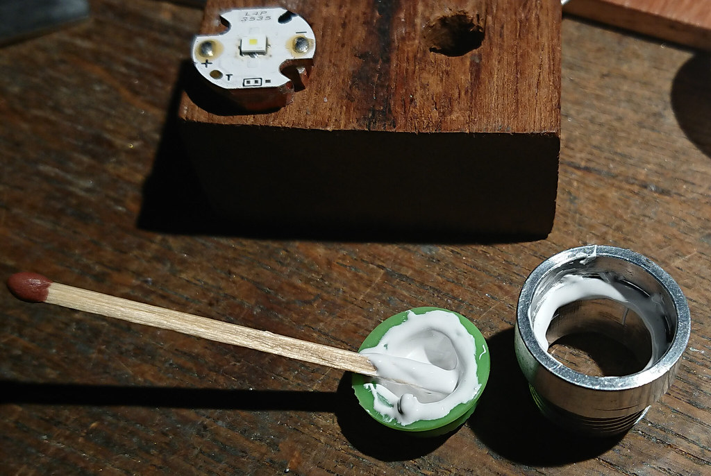
glued in, pushing hard onto the board during the curing of the adhesive to make as much as possible direct metal-metal contact
I tested with the led-tester if all worked without unwanted shorts to the pill. 
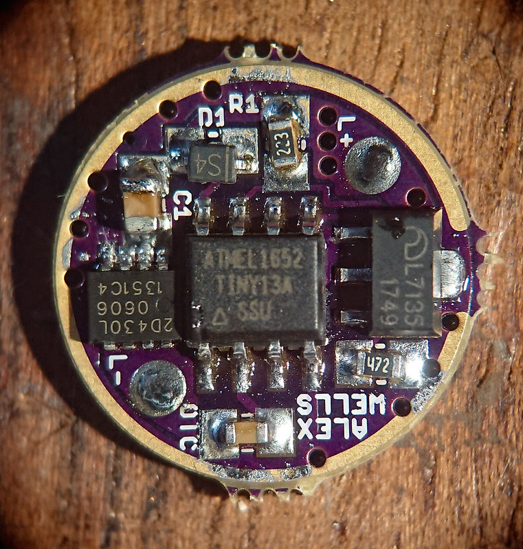
The driver.
I decided on a BLF-A6 FET+7135 driver, but leave enough resitance in the flashlight to not overdrive the (very low voltage!) Osram KW CSLNM1-TG led. The BLF-A6 driver is a 17mm driver and can not be sanded down to 15mm for this flashlight, but WarhawkAWG a few years ago had made a 15mm version of wight's FET+7135 driver (Oshpark link) that works well with the components unsoldered from the A6 driver, except the FET is too large and should be replaced by a smaller LFPAK33-package FET (bought from Mountain Electronics some years back).
solder paste was applied on the new board.
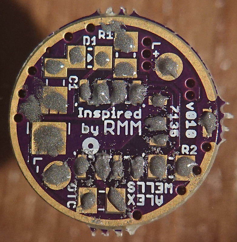
The yellow BLF-A6 board was put on the hotplate and the components one by one transferred to the 15mm board (except the FET, that came new).
The reflow, accompanied by my talented son  who is learning himself how to wistle

result
it works with my test-led

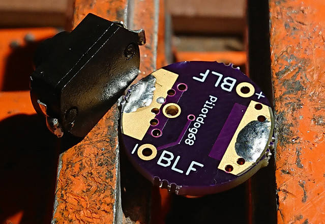
The pill has no driver retaining ring, and being aluminium, can not be soldered to. So the driver needs to be press-fit. I have my method to make the driver pressed in and at the same time provide good ground ring contact with the pill. First some notches were filed in the side of the driver and pieces of thin (nickle-plated) copper wire were stuck inside a via and bended around the side of the driver to the battery side (top of the wire-pieces were filed flat a bit)
the wires were soldered in on both sides
and the result was filed in shape so that the component side of the wire pieces was kept very flat, and the side was sticking out a bit to clamp in the driver cavity of the pill.
The driver just before pressing it in with my orange vice
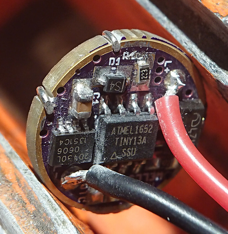
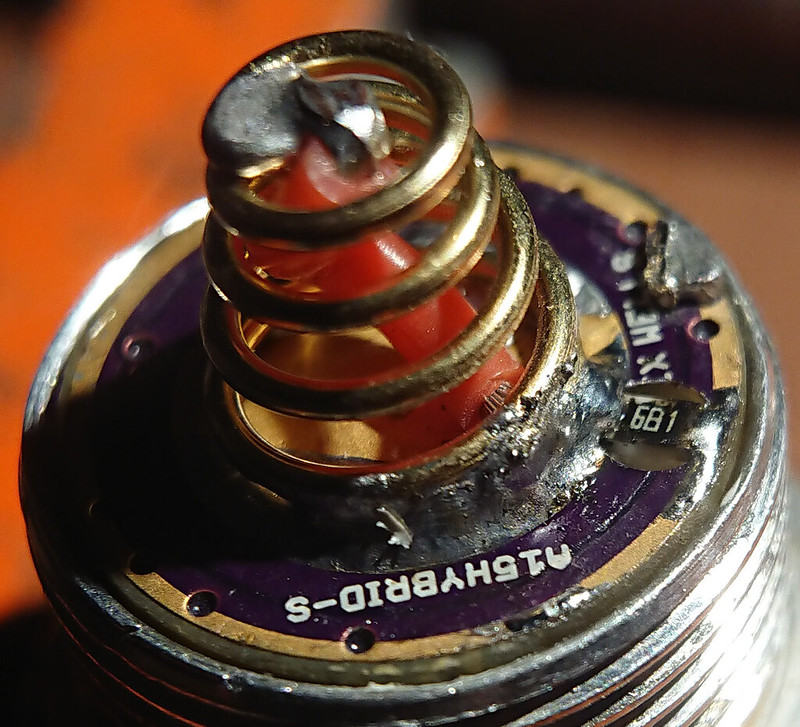
pressed in tight, will not go anywhere, spring added, and spring bypass soldered (22 AWG wire). Later I have removed the bypass because I found the current too high
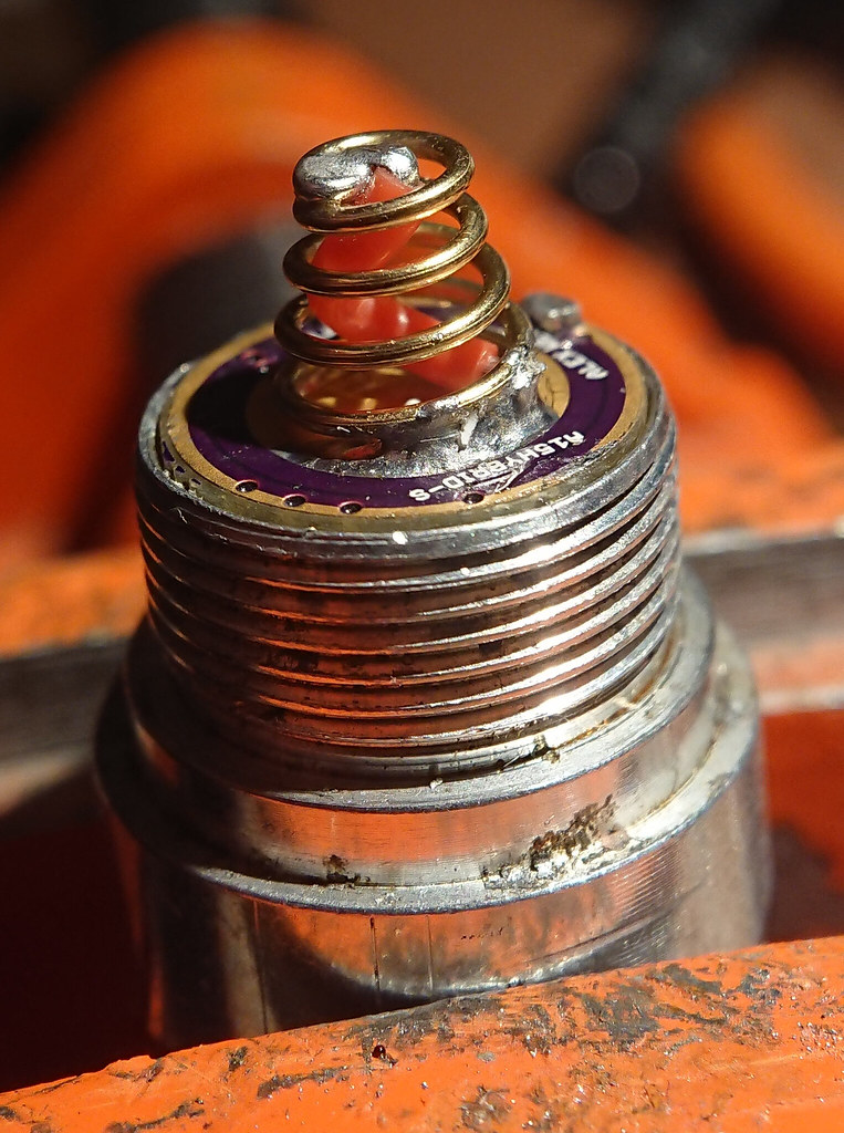
I forgot to add a bleeder resistor to the driver (the flashlight will have a lighted tail), so I drilled a shallow hole (dia2,5mm) on the battery side and crossed the ground ring and batt+ pad with a 680 Ohm resistor.
I tested the finished pill with the led tester (a led tester will power the driver enough to make the user interface work) and all was working
The tail
I do not trust the stock switch very much at high current, and also I wanted to do a lighted tail. So the stock tail on the right must go, and it must become one like the one on the left. The height seems about correct.
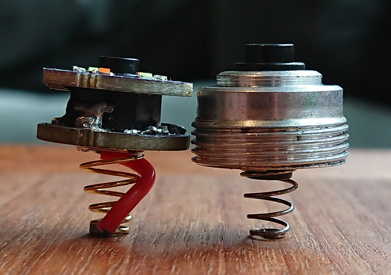
But the switch assembly like on the left needs a retaining ring and there is none for this specific flashlight. So I made a retaining ring out of the original switch. First I pushed the switch out of the aluminium holder. Then a pieces containing the threading was cut off with the band saw (a hack saw would have worked just as well).
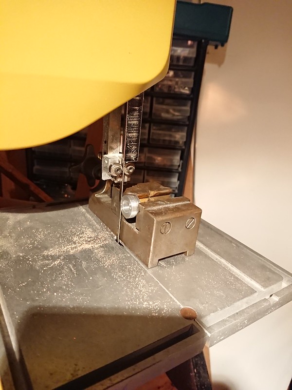
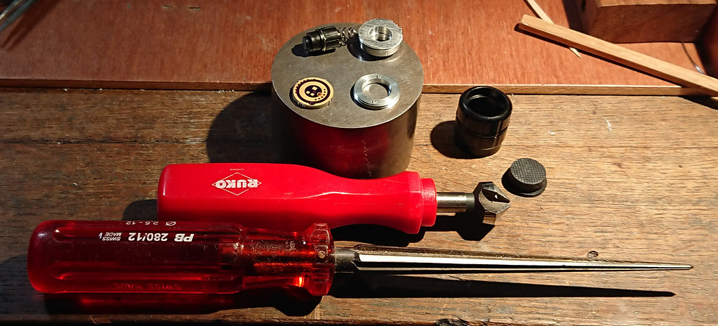
The cut-off piece was sanded flat with sand paper (on the flat iron block) then the inside that was way too narrow was reamed a lot with a hand-reamer. For grip on the piece during reaming, it was screwed into the tail-section of the flashlight that was held firm in the hand with a piece of rubber inner tire. The inner edges were bevelled with a countersink tool.
result
An Oshpark tailboard by pilotdog68 (link later) was used for soldering the switch (Omten 1288) and spring. I always pre-tin everything, then fuse with the solder iron. In case of the switch I solder very fast, to prevent melting the inside of the switch and kill it. Also, the spring is soldered first before doing the switch, so that the heat from the spring soldering can not kill the switch.
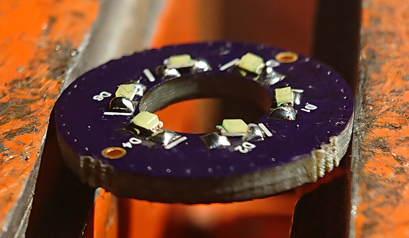
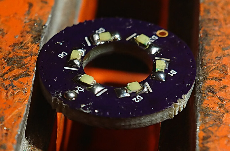
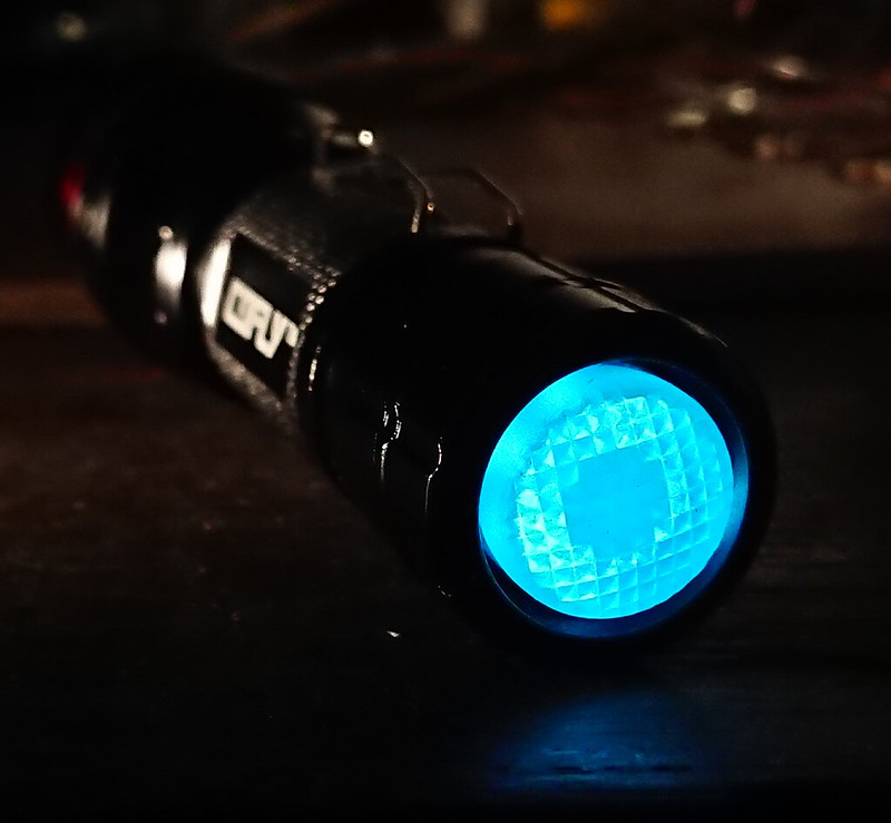
I used a 6-led ring board for the tail leds, made by Lexel. it has pads for two potmeters on the back, but I simply soldered fixed resistors there (2x 8.4 kOhm). The leds are ice-blue 0603 leds. If 10 minutes of your life watching soldering is not too boring  , off you go:

ok, it worked but it was not particularly nice soldering
so I did it up a bit after the video
I had a few tail leds fail over time and I think it helps if the soldering is good.
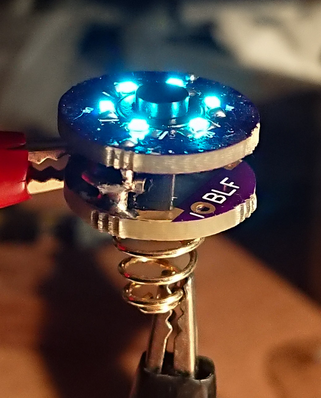
Two very short copper connection wires were soldered in the ring-board and soldered to the switch-leads. tested with the led-tester, it works :-)
all screwed in
Assembly
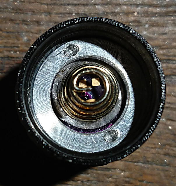
The light was assembled, and before closing the lens, the top and inside of the pill was blackened with a black marker, while being careful not to touch the die
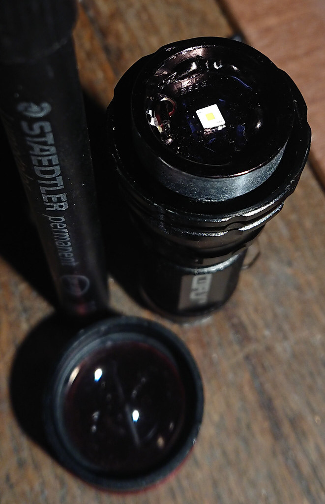
Although the new ledboard is thicker than stock, the focus of the beam in spot modus was correct, so no lens height adjustments were needed.
Finished
performance
I had chosen the bleeder resistor value and tail resistor values well so the user interface was not messed up (I chose the BLF-A6 driver and not the X5/X6 driver because it is less critical about that).
I measured output without tail with a clamp meter and got over 6 amps. With the flashlight on the highest setting the light was clearly getting a bit blue. Even with the extra resistance of the tail the current was too much, so I removed the spring bypass on the driver. Then there was no blue shift of the tint anymore.
The output zoomed out on a purple Efest 14500 is 400 lumen, zoomed in 170 lumen.
The throw with the driver spring bypass still in place was 68 kcd (measured at 30 seconds on a full battery), with the bypass removed it was still 65 kcd and I reckon the current is now just under 4 amps with the battery full. Much better for this small light, but still it gets hot pretty fast, the build-in stepdown of the BLF-A6 driver after 40 seconds is much needed (and adequate).
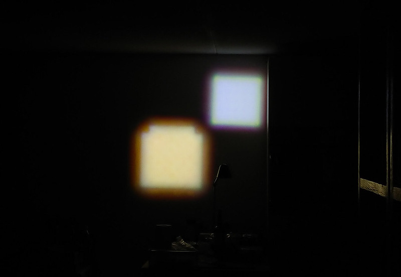
The beam is plain white (unlike beams of dedomed XP-G2's) and zoomed in very very square . You can see vaguely the die pattern, especially on low modes.
(left Cofly zoomie with dedomed XP-G2 S3 3D (well over 4 amps), right Cofly zoomie with KW CSLNM1-TG led (just under 4 amps)
conclusion
I'm really happy with this version, the throw is again a bit better than with a dedomed XP-G2. The new led is not at its maximum performance, perhaps I should have soldered it more critical, but also in this host there is not a great heat path. Nevertheless I think this is quite the thrower for its size :-)
I hope this post with the many pictures and video's was fun to read. I may still edit it here and there in the coming days, or add even more pics.
