I did suggest a chip that could do the charge and powerbank without MCU connection, and can cope with flakey intermittent solar input, and has a pedigree, and is available, and inexpensive.
But I can’t remember. It’s here in the thread somewhere. Just look up my posts, It’ll be there.
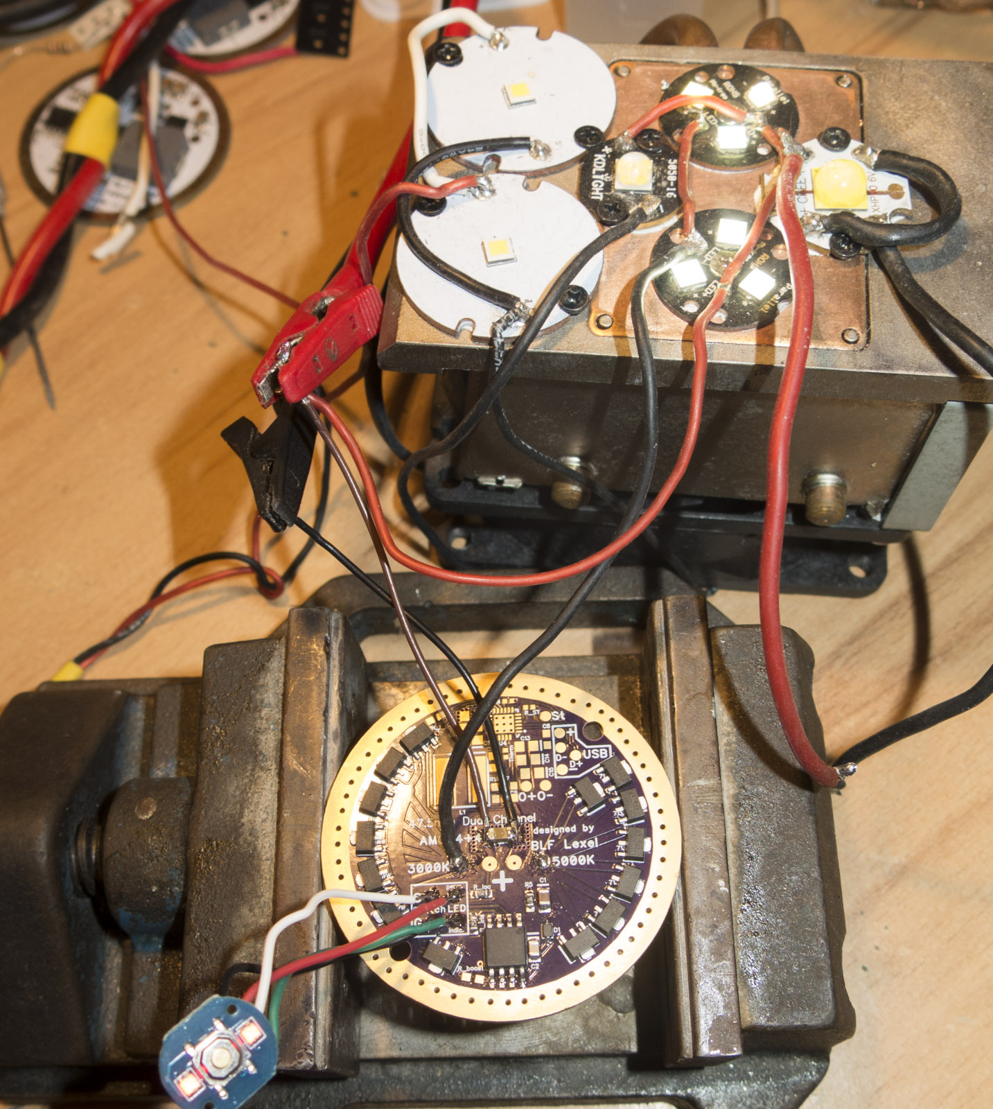
I admitted I might be wrong, but the design I see above looks like it is power bank and charging capable with a single IC, which is U4. I do recall that the current firmware hosted on the ATTiny85 has limitations in controlling all that could be done in this driver. I don’t see a driver that is providing just a charging function. I am pretty certain that the design is the same as the one DEL generated a year or more ago, and was provided to Lexel.
But to be certain we need Lexel to clarify this IMO.
I know we discussed dropping the power bank for this model in the team chat, but i was sure we all agreed to keep the charging feature, which is a key feature needed in this type of light as a very usable feature for long-term use & off-grid use. (will hope he chimes in on that soon.)
Powerbanks are simple stuff, though they do need a good standalone power management chip.
No need to tie it into the MCU unless you want (and know how) to reconfigure things into the latest high power charging and discharging modes. 5V at 1-2A through up to three outputs is usually enough.
Aww, that’s a bummer. I was really looking forward to the power bank functionality. I understand if it can’t fit the equipment/schedule for this first version, and USB charging is still nice, but still. Bummer. Thanks for all the hard work though guys, I’m still interested in the one I’m on the list for.
AT&T came up with a USB charger that would have “zero” vampire draw in 2010.
I think it had a solid-state relay before the rectifier/transformer and a capacitor after, and when the capacitor was full, it’d open the relay.
Plug USB device into charger, capacitor discharges, relay closes, device charges.
Unplug USB device, capacitor reaches charge threshold, relay opens until USB device is plugged in or the measurement circuit discharges the capacitor beyond the trigger threshold.
I may still have one of them laying around somewhere.
v2.0 designed, sleep over it and see if any errors accured
updates:
Power bank stuff removed
+ TP5100 2A charge chip installed
added on battery side a solder pad to switch between 0.75 and 1.5A
added + and chrg and full pads for Charge light indication
+ AMCs can now individually added or removed by pads on the battery side 3 AMCs per channel fixed up to 7 can be unlocked by bridging the solder pads with solder blob
May I request that 0.75A charging be the default, to minimise the chance of crashing a small solar panel?
I’m sorry to see the powerbank function go, but I’m still planning to buy at least one of these. I’ll decide what to do next once I’ve been able to play with the first one
for first version Powerbank got removed installing a simple charge board, then the preassembled charge boards were too big to reflow them onto the driver,
so it went on it as parts at least so we can control the quality of the used parts
default will be 0.75A
from the space also 0.5A, 1A and 1.5A would fit with 2 solder areas and 3 shunts, but I think 2 are well enough