Out of the box quite nice. Great fit and finish and nice compact size. No sign of blue-shifting tint when I used the partially charged cell that came with the light.
But then I used the built-in USB to fully charge the folomov cell and PROBLEM!!! When turned on in turbo the light blue-shifts within 5 seconds and output drops dramatically. Instead of 800 lumens it looks like its only outputting 100 lumens.
Once the light is warmed up by having been turned on and off for 5-10 seconds, the problem is worse. Turning the light on while it is warm causes the blue shift and reduction in lumens to happen almost instantly (less than 2 seconds).
and all of this is with the cell that came with the light! It’s not even a high discharge cell I assume.
My guess is the LED simply can’t take the amps. Either that or the LED is defectively installed. If anyone can get the head open it might be worth swapping the LED to something else. Perhaps XPL HI.
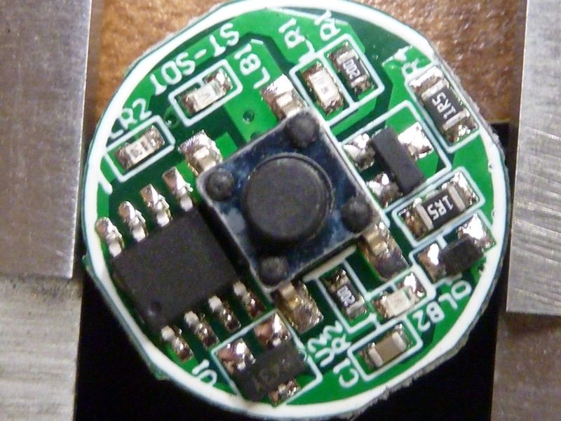
The most interesting thing about this light seems to be its tail-mounted driver with no extra channel to run BAT+ back or run the switch signal forward.
How does that work? Does it seem like something which might be useful for BLF designs?
I agree. I’d LOVE it if someone made a tail mounted e-switch driver that didn’t need the extra channel and sold it on Mountain Electronics. :heart_eyes: :heart_eyes: :heart_eyes:
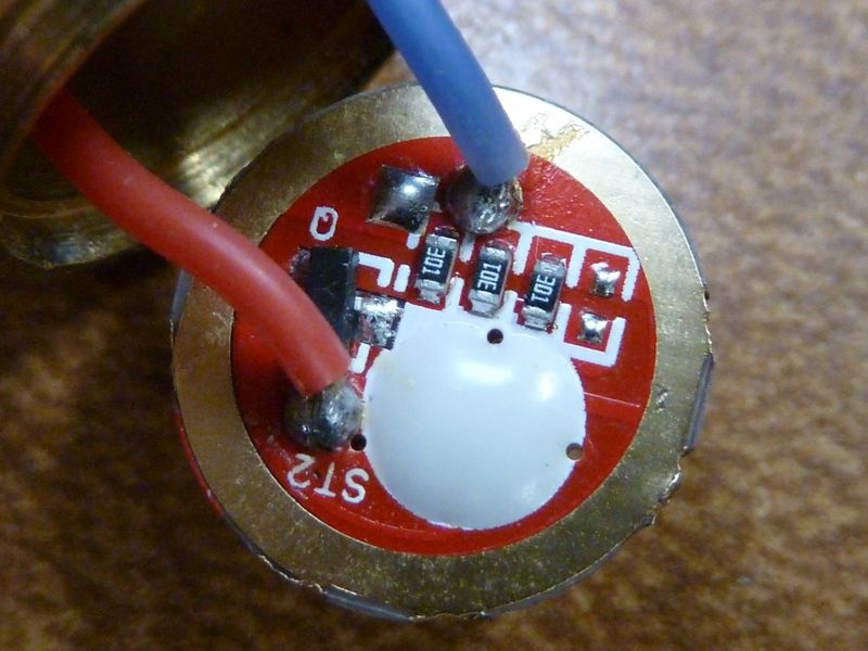
I agree - it's fairly unique, but I think the UltaFire UF10 had the same design. Here's the UF10 driver from the tail:
I really like the UF10, same sort of tail e-switch, but much simpler UI. All I did was swap the LED/MCPCB,and maybe wires to get more output and added bypasses.We use it about every night with the dog.
Ohh, this is the PCB at the head, so there are some surface mounts but no smarts, I believe:
This info is disheartening.
I ordered one which will arrive tomorrow after the all clear was given.
Maybe I’ll get lucky with my sample but Not going to keep a flashlight that can’t be dis assembled to fix.
How does the flashlight operate with other cells?
Thanks
Actually, I think the fully-charged cell might be providing too much voltage to the LED.
After running the light another couple minutes on and off I notice that it no longer seems to blue-shift and dim. So the issue seems to occur with the fully charged cell.
Anyone figured out how to change the LED in the 18650s yet? From looking in the back of the head it looks like a press-fit plastic washer might be keeping the guts of the light in place.
Well, that's not press fit plastic. It's a black painted LED isolator glued to, what I think, is a shelf. I got the isolator ring off and it exposes threaded screw holes with screws in them from the top. Only way they could do that if the front end bezel comes off - suspect it's glued,very hard to see where.
Nothing magic done there. If the driver is completely in the tailcap it can work. think about that way that the tube is the led negative wire. The led positive is directly connected to batt+ and that is all. So the head only have a contact PCB which connects batt+ to led+ and tube to led-.the circuit is the same just the driver location changed in the light. The only drawback I see that is not good for high power lights because you can’t measure heat at led. If thermal sensor is in the controller it takes a lot of time to sense the heat. The only working option is timed stepdown. I hope I soon get mine and make an X-ray photo from head to see if there is any parts in there other than only a PCB.
Just look at the UF10 batt+ contact board above, and what I stated couple times earlier of measuring 51 ohms between batt+ brass button and the head housing, so there's current running through there. The UF10 has that hidden "thing" under the white hardened goop -- hhmm.
John from FB said: Mine turns blue and it gets quite hot. I've never seen one turn that color before and thought maybe mine was the only one like that. I'm going to see if I can get my money back. This is my first and last Folomov.
I emitter swapped my Folomov 18650s today. :sunglasses:
This fixed the issue I was having with the emitter blue-shifting and getting dimmer with some fully-charged cells. Turns out the 219D just can’t take high current.
No pictures, but here’s how to emitter swap the 18650s:
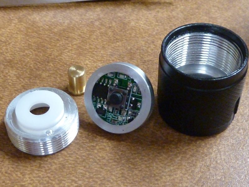
The head looks like it’s in one piece, but it really isn’t. The bezel is the smooth portion ahead of the fins on the head. It’s just screwed onto the head. I applied 3M indoor stairway grip tape in a ring around the head and another around the fins and unscrewed. The bezel came off easily. There was no glue, but there is an o-ring.
With the bezel and lens removed, lift or tip out the smooth reflector to reveal the star.
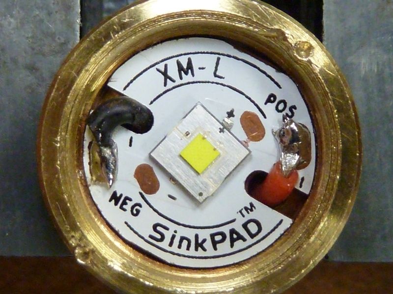
The star is copper and is screwed onto the full shelf on the head with 2 screws. There is one wire connecting ground to the star. On the back of the star is a soldered post that directly contacts the top of the battery. The star also has 2 resistors on it. There is no other board at the head of the light. The driver is in the tail.
Desolder the negative wire from the star, then unscrew and lift out the star. Some thermal paste was used under the star, but more would be better.
The hardest part was heating up the star enough to remove the emitter without the post on the back getting out of position. I used a wooden clothesclip held sideways in a vise to grip the post on the bottom of the star, then used hot air reflow to remove and replace the emitter. I replaced it with a XPL V6 3D that I had laying around. I might end up replacing this later with an XPL HI for more throw.
I also added a copper disk onto the bottom of the post at the bottom of the star to allow flat-top cells to be used.