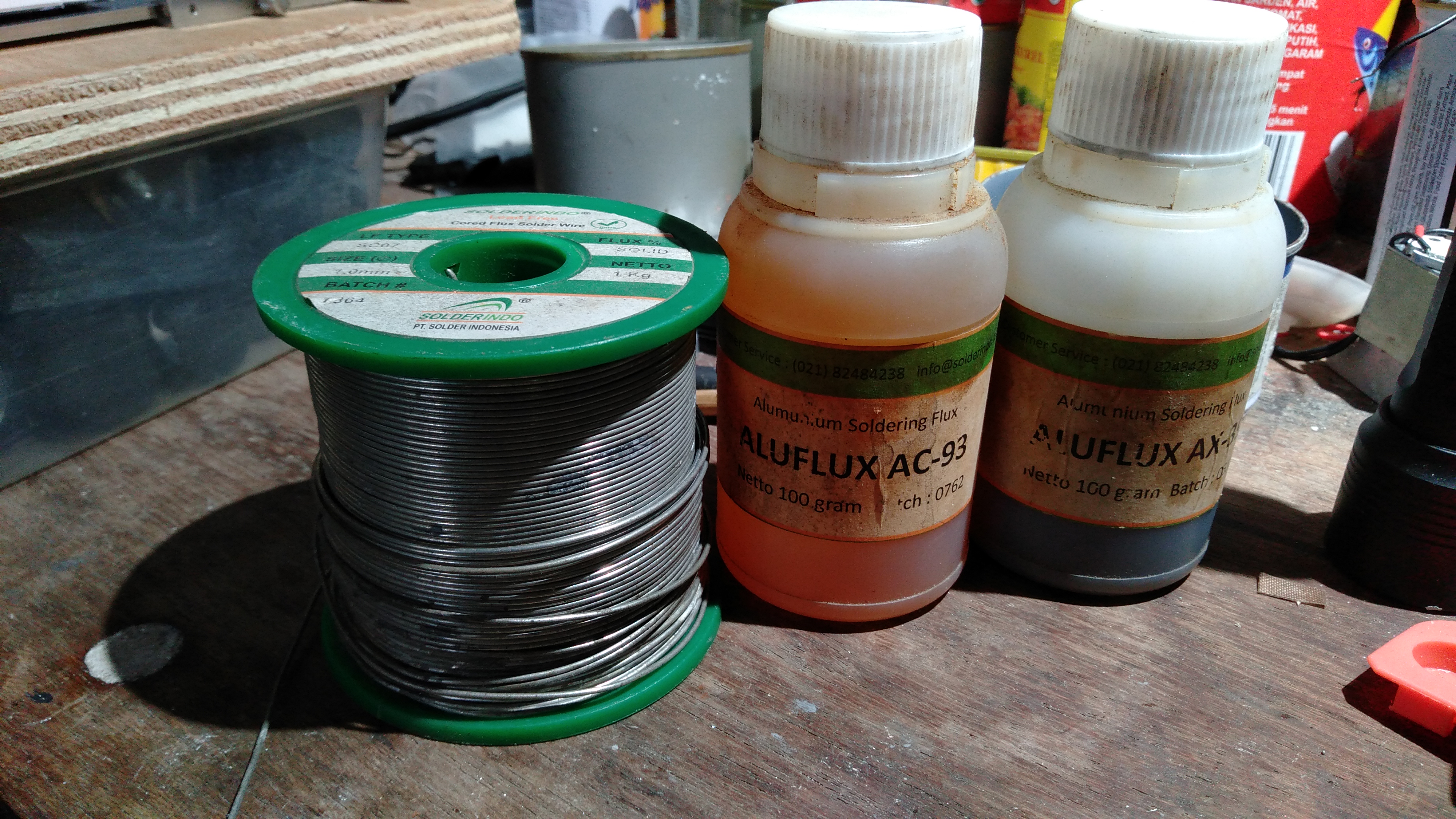
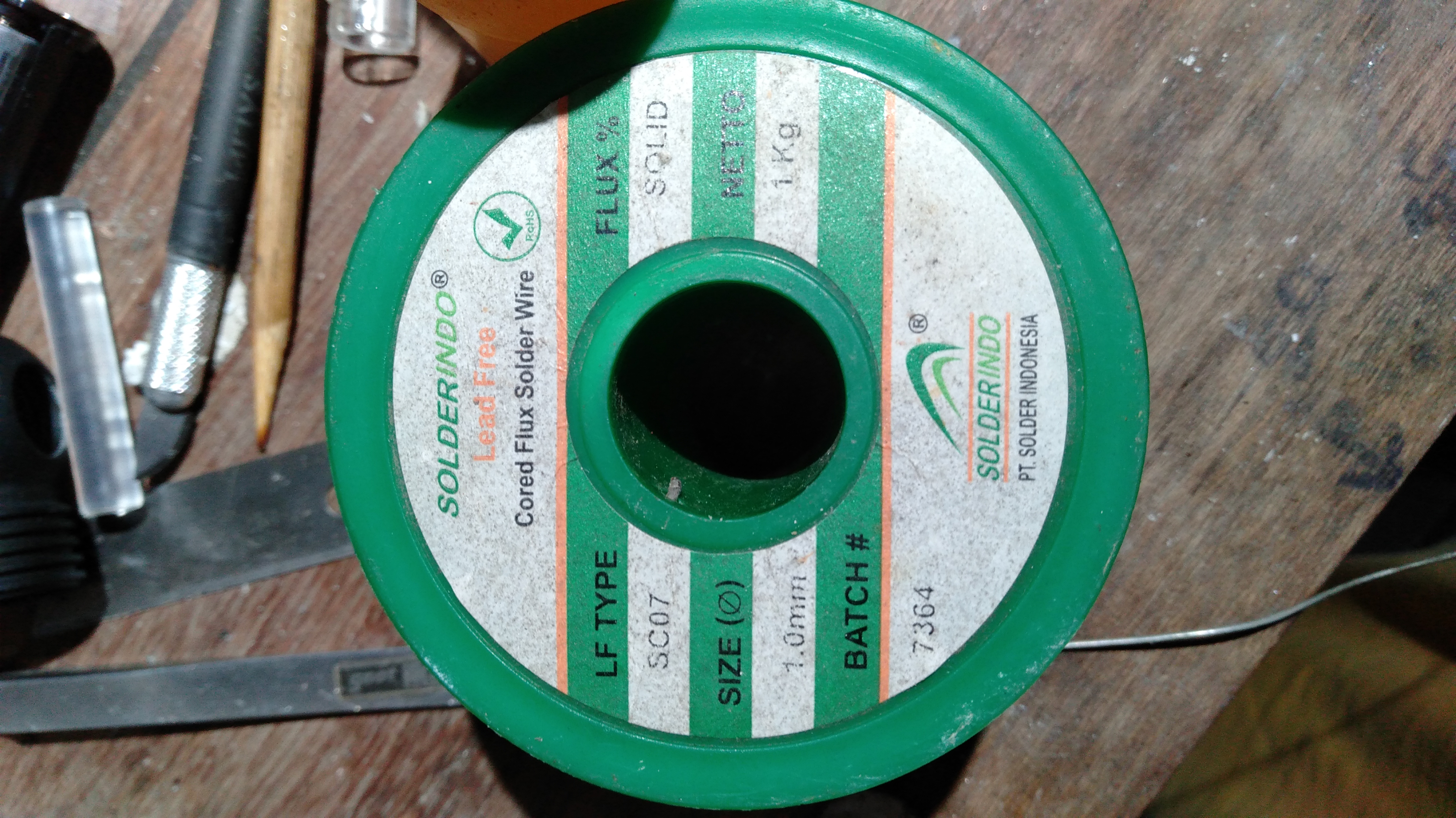
Known as SC07. Good for soldering aluminum. High melting point, but very strong joint. I have 250gr 0,7mm spool lying unused. Bought for it’s “slightly” better thermal conductivity but the higher melting point made it my last choice.
- Clemence
Known as SC07. Good for soldering aluminum. High melting point, but very strong joint. I have 250gr 0,7mm spool lying unused. Bought for it’s “slightly” better thermal conductivity but the higher melting point made it my last choice.
- Clemence
If you don’t plan to remove the LED later, then we can easily braze the chip directly to almost any metal. The brazing material can be anything with melting temp lower than 1500°C. Copper or Silver is a good candidate.
- Clemence
But such temp will destroy the phosphor. Maybe a die as well.
Can someone explain how to wet aluminium with Sn99.3Cu0.7? Tried to do it over heatsink material in the past, to no avail. I can understand it has to do with the particular aluminium alloy of the heatsink, maybe some 6061 crap, and insufficient surface sanding down. Hello?
Cheers ^:)


Nanofoil
Asked for sample but heldback because the solder still limited to Sn based
https://www.indium.com/assets/videos/nanofoil/nanofoil-reaction.mp4
- Clemence
I’ll post a pic and video for you guys. But, I have to modify my hot plate (cloth iron) to 260ºC first. It’s only maxed at 210ºC. Rarely use lead free solder these days.
- Clemence
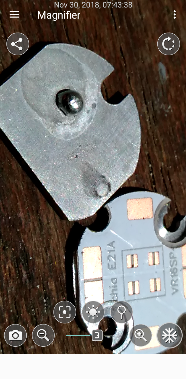
Tried to wet large area with SC07 and 60/40 at 260ºC max. and the result was not successful. I could only wet no larger than 3mm diameter blob. With 60/40 the blob was larger and easier but 5mm was the largest I could get. I had successful result but that was using my stove hot plate at 320ºC which I no longer have. Already converted the stove hot plate to a clamping fixture on my mini milling machine. ![]()
FYI, soldering aluminum with Sn based solder is not reliable, unless there’s a continuous voltage in the junction to feed the galvanic difference. Adding Zn in the solder will last longer. I don’t recommend soldering aluminum directly in everything elsa but mechanical or structural projects. Most aluminum fluxes requires high temperature to properly activated (300ish ºC). The most successful way to solder aluminum in electronics is to first plate the aluminum with nickel - gold or copper.
- Clemence
Another thought….would vapor chamber work as a PCB base?
Plating aluminium with copper but what kind of aluminium we're speaking of here? The aluminium used to craft heatsinks or flashlights can be some sort of suckass aluminium alloy which won't plate easily, so I hear you better first zinc plate it then copper plate or something like that. ![]()
Cheers :-)
A quick followup on the pure Indium:
I’ve really come to like the stuff, it makes reflows much less stressful especially with larger MCPCBs. You’re nowhere near the point where the emitters start to degrade and PCBs delaminate so you can take your time.
It also helps a lot with soldering wires where a large thermal mass sucks heat away quickly, which sometimes is unavoidable.
Yup, really like this stuff too, except for it’s steep price
- Clemence
That’s a bit OT but I really like soldering leads with SbBi.
Only for leads, never use for this Sn42Bi58 for attaching LED. It has very bad thermal conductivity, approaching that of stainless steel. Somewhere around 16 W/MK. I usually mix some with Sn60/Pb40 to make melting point slightly higher. 138°C is too low
- Clemence
540W/MK is outstanding! So does the price I guess. Its so hard that only EDM machinable which is very slow. I machine a 2mm, 45mm deep oil passage in a hardened race bike’s crankshaft few years ago. Precise control and diameter tolerance was an issue.
- Clemence
And another…:
http://www.rhp-technology.com
This one does only Cu/Diamond:
http://www.sumitomoelectricusa.com/products/heatsinks/copper-diamond
The first one that I found would do 400 PCBs (that’s their MoQ) for mere $14K.
Maybe others are cheaper…anyway it shouldn’t hurt our record-chasers to ask for samples. ![]()
The Copper Diamond is the most interesting because it can be metalized while still electrically non conductive. With 650W/MK thermal conductivity the thermal bottleneck could the solder itself (assuming non gold plated contact used). In my opinion thermal resistance is more relevant since in the end this is what matters.
If an attachment system thermal resistance can be optimized to slightly below the thermal resistance in the LED (which we can do nothing about) then the rest of the system can use that number as the minimum resistance. In my opinion, as long as the cooling still creates negative delta temp copper or aluminum heatsink still doing OK. The higher the thermal conductivity of a material the less delta temp needed to flow the heat. We can make a superior cooling system using available budget friendly material widely available with good design and process. Manufacturers have to compromise the outcome to balance the design for a reasonable total cost.
For example:
- Use the best solder available (Indium is in the top of my list). And don’t forget to make the joint as thin as possible.
- Use the thinnest most rigid substrate possible. Metalized Aluminum Nitride can be made reliably down to 0,2mm without sacrificing rigidity. Although the thermal conductivity is only up to 180 W/MK in most cases, the thin substrate will make up the difference. This is demonstrated clearly in my MCPCB using “low” aluminum oxide dielectric with only 7,5W/MK thermal conductivity. Thermal resistance is what matters.
- Conventional wide and thick copper traces still works to further spread the heat over the entire board substrate as long as the radial thermal resistance still lower than through plane resistance.
- As flat as possible finish in the substrate and heatsink mating surface makes a big difference. Don’t compensate with thermal paste. Get the best possible mating surface first, use the least amount of thermal paste.
- Clemence
The last manufacturer until I find some new search terms:
http://www.awindiamond.com/eng/04_application/Laser_HeatSpreaders_CDHS.html
Clemence, I don’t think that it makes sense for manufacturers to go beyond the standard SAC305. And definitely not now when even enthusiast haven’t demonstrated any improvements, only calculated some tiny ones. I’m not sure what budget materials do you mean but as far as I see budget light makers already do quite well when it comes to LED thermals. There may be tiny improvements here and there, but better materials don’t seem to be a budget choice.
Well, I imagine one possible improvement. That’s likely not a good idea anyway, otherwise saabluster would do it years ago. Eliminate MCPCB. Machine the shelf to leave a protruding thermal pad, add insulation on the rest of the shelf and make anode/cathode connections.
Or make the MCPCB several mm thick and press-fit into the head. Just like Nightwatch press-fits copper heat sinks.
Moving to Indium will only make manufacturing cost higher. Its inline with Pb Free regulation. Indium Corp. offers pre cut solder that can be used in normal fluxless nitrogen reflow chamber.
This approach still not feasible for real budget products but has its place in professional products. I know Saabluster idea and its already followed by Manker E01 but there’s still solder involved. I did an experiment with successful result with XPG back in 2012. I electroformed copper to cold weld the thermal pad directly to the copper heatsink. But the process was tedious and took too much time to make it feasible in any of my later built. It’s also permanent and can’t be undone without destroying the LED
- Clemence
I don’t know what idea you’re referring to…what interesting does Manker E01 do w.r.t. thermals?
I’ve seem solder preforms from indium, but didn’t think much about them. Yes, they surely seem doable for a serious factory.
I’d like to learn more about your electroforming experiment, is there a writeup somewhere?