Perfect for Cree XM-L series LEDs -- especially with T6 and U2
Dual PCB layout, 10mm total height
Designed for Cree XM-L LED emitters
Also works with four MC-E's and four SST-P7's connected in parallel
2800mA maximum current output
Low voltage warning battery protection mode triggered when voltage drops below 3V (in 1-lithium configuration) or 5.8V (in 2-lithium configuration): automatically switches to the lowest output setting, and blinks periodically
Modes:
Group 1: Lo (5%) > Mid (50%) > Hi (100%)
Group 2: Lo (5%) > Mid (50%) > Hi (100%) > Strobe > SOS
To toggle mode group:
Switch to Lo (5%) mode and count exactly 5 seconds. As soon as the flashlight blinks, half press (or quickly toggle power) to go into the other mode group.
Measurements
Tested with: Cree XM-L2
The driver uses buck mode
Driver diameter 18.6mm + 21mm
Driver height 8mm
The driver has memory, the actual mode is stored when the light is off for a short time.
A off/on will select next mode, the off has to be rather long, not to select next mode.
Mode set 1: High, medium, low, Strobe, SOS
Mode set 2: High, medium, low
The driver can be used with 1 or 2 LiIon batteries in series.
Strobe is 15Hz with 43% duty cycle
Threshold between 1 and 2 cell is between 4.5 and 5 volt
High
The drivers has very good regulation and good efficiency. It turns power down at 6.7 volt and battery warning comes on at 6 volt.
There is a maximum of 1.5 watt lost in the driver, while delivering 9 watt to the led.
No noise in the light.
The low voltage warning is a slow flashing.
With one cell the stabilization only works down to 3.7 volt, that means no stabilization for half of the runtime on a single LiIon cell.
The driver has a low voltage warning at 3 volt.
Medium
Medium has the same good stabilization and does not step down, it goes directly to low battery warning at 6 volt.
The led power is down to 2 watt.
With lower led power, the driver can sustain the medium level down to about 3.2 volt and it has very good efficiency.
Low
The regulation is also good on low, but the efficiency is slightly down.
With a single cell the driver works down to about 3 volt with full stabilization, before it goes into low voltage warning.
Strobe
Strobe is 15Hz with 43% duty cycle, the driver cannot reach full brightness with a single cell
SOS
Conclusion
The driver is a very good stabilization (Except on high with 1 cell) and good efficiency. The mode change could be better.
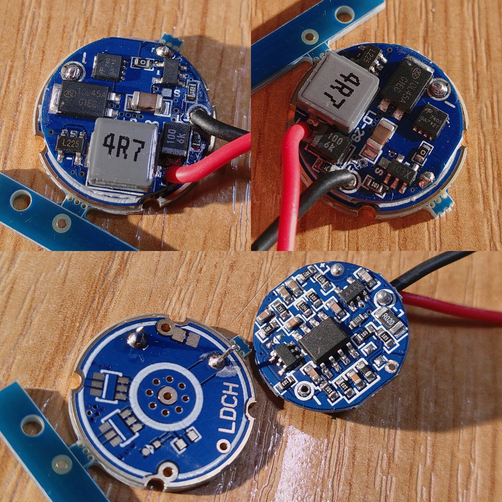
Took a few close-up pictures of an LD-29 received from FastTech a week or two ago, combined them in a picture:
Some changes can be seen, among them the usage of an R020 current sense resistor (which means 60mV :THUMBS-UP: sense voltage). The daughter board features component slots for… reverse polarity protection MOSFETs maybe?
I have a modding question: what are my chances of considerably increasing the current and power output of this driver? Let's say I aim for 7,8A current output LoL by stacking 4x additional R050 current sense resistors. The onboard schottky is rated for 10A so it should survive (?). The inductor looks insufficient to me, I can swap it with a much bigger 2R2 (10,2mm side lenght versus 6,8mm of the stock 4,7µH unit) or maybe go the extra mile and install a motherboard scavenged super high current R60 unit.
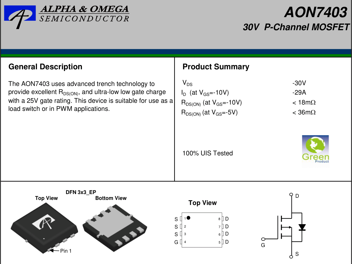
Main problem, as far as my understanding goes, is the AON7403 MOSFET switch. Do you think stacking another one above it with a tiny heatsink could be enough? I've checked its VGS versus resistance graphs and it doesn't seems appropriate for 1S input operation at all… :facepalm:
Also cheaper than the AON7421, but way slower switching speed though. tr + ton + tf + toff is 198ns for the AON7421, 617ns for the TPN4R712MD.L1Q, and just 42,2ns for the AON7403. The buck converter frequency is probably ≈300KHz, I wonder to which point do these parameters matter.
Besides changing the current sense value my wild guess is that I should swap the switching MOSFET, the inductor and maybe improve input and/or output capacitance (?). This should allow the buck driver to operate reliably at much higher currents because of much improved output noise and reliability.
That buck controller is an XC9221, you’ll find guidelines and the relevant formulas in the datasheet here.
I think 4.7µH is already on the low side for 300kHz, any lower might cause stability issues, but if you can fit a bigger size inductor anyways you can up the current rating at that value.
I don’t think switching speed of the FET is that big of an issue at 300kHz, but what matters is the input capacitance (recommended <1500pF), otherwise the controller can’t drive the gate fast enough. (That’s where the Toshiba shits the bed)
btw, Vishay and TI have very good FETs (like the CSD25402Q3A )
PS: If you’re using this in a 2S setup anyway, does the Vgs@2.5V matter that much? I don’t think so
Thanks for the input kikkoman, seems the XC9221 wasn't designed for higher than 3A output and I want to make it go a lot beyond }D that LoL. Thank God at least the schottky O:) is generous.
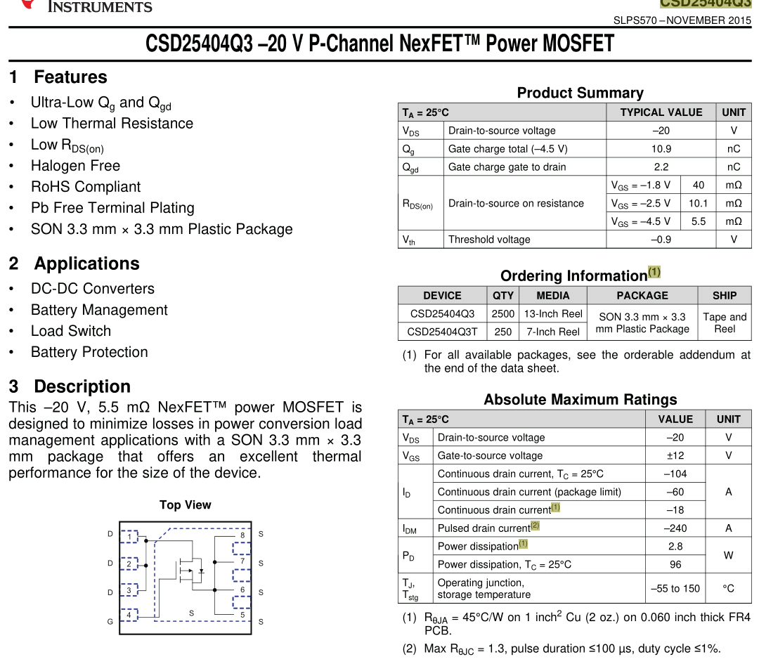
There’s its brother, the CSD25404Q3 - slightly lower Rds, slightly higher gate capacitance (but still quite low), and it’s a bit pricier. 0.95€ for 1.
I really can’t tell you though how ‘set in stone’ that current limit is. There’s no internal current limit, so aside from external components (= available space), I guess the gate driver is the one limiting factor.
Guess will have to try that CSD25404Q3. The input capacitance is specified at 10V, it should be a bit lower at a bit less voltage, doesn't it? Also, the QX9221 shouldn't complain if a little bit above 1500pF…
To round this off, took a peek at Murata's inductor catalog. Their FDA1254-H-4R7M=P3 seems to fit the high current bill (LoL with the model naming). €2,01 a piece… :facepalm:
Just ordered 3x FDA1254-H-4R7M=P3 inductors and 3x CSD25404Q3 MOSFETs. Didn't asked this before, but I guess improving input and output capacitance is also advisable, doesn't it?
Stock input capacitance is 22µF and I have 90+ pieces of capacitors like the stock one inside a drawer. Also a handful of 47µF tantalum caps which may go well at the output…
Will have to put a name to the badass, maybe LD-29.9 LoL.
There’s no real downside to increasing the input capacitance I think, but output is different. If the ESR is too low, you’ll get load transient issues. I wouldn’t go overboard with that.
If you have a scope, you can check if output ripple is within acceptable limits (if it is, then there’s no reason to increase C_out).
Free overnight shipping @ Arrow is great but there are distributors that are cheaper in the end (even with shipping) where comparable inductors cost 1/4 of the price.
Could add another input capacitor in parallel without much trouble.
What do you mean with output load transient issues?
No scope right now but since I aim for 3x the stock current output, I'll fit some extra capacitance.
With regards to getting a scope, will have to consider this. Something affordable :-D and good. I have not much idea of the features I should mainly care for with the exception of price LoL.
Connected my small 219B plus heatsink testing mule to it and supplied power (≈8.2V) with DC supply, sticking a normally closed push button in the middle for mode change.
Of course I set some current limit in the supply just in case. The emitter started being lit very faintly, and its output started ramping up until the supply hit the current limit at more current than it should pull with the stock sense resistor value. I used the switch a few times and it seemed to enter some sort of weird strobe mode at some point, but continued hitting the switch. I raised the current limit a bit and then I left it doing what it was doing once or twice more for some seconds and all of a sudden it all stopped, with some very subtle burning smell I'd say.
Could it be that the buck converter was unable to properly drive the MOSFET gate?
I was toying with the idea of modifying another one of these, found a well suited inductor in the Bourns SRP6050CA-4R7M. However, I have a few qualms with the newer LD-29. The AON7403 MOSFET's low VGS (3 - 4V) performance seems much worse than that of the FDS4435 according to datasheet curves. I wonder how much of an impact will this have for 1S operation due to the much higher input current handling. Not being a scaremonger, just a little tired of burning stuff up. It would also help if manufacturers would stop spoiling their products (are you hearing LDCH?).
Been peeking into some small package p-channel MOSFET datasheets with low input gate capacitance. There are some better offerings over the stock AON7403, the Infineon IRFHM9391TRPBF for example. However, all of them exhibit noticeably lower performance at less than –4.5V of VGS, and already a lot lower at –3.5V. I am surprised at how this driver did not have some problems on high mode with less than 4V of input, but of course this is due to the relatively low input current. Sucks, really.
/DSC_4065a.jpg)
/DSC_4067a.jpg)
/DSC_4066a.jpg)
/DSC_4068a.jpg)
/DSC_4069a.jpg)
/DSC_4070a.jpg)
/DSC_4071a.jpg)
/DSC_4072a.jpg)
/DSC_4073a.jpg)
/1-2%20Lithium%202-Group%203-5-Mode%202.8A%20LED%20(LD-29)%20HL%208.4V.png)
/1-2%20Lithium%202-Group%203-5-Mode%202.8A%20LED%20(LD-29)%20HL%208.4VDriver.png)
/1-2%20Lithium%202-Group%203-5-Mode%202.8A%20LED%20(LD-29)%20HL%208.4VLed.png)
/High%207.2V.png)
/LowVoltage%205.9V.png)
/1-2%20Lithium%202-Group%203-5-Mode%202.8A%20LED%20(LD-29)%20HL%204.5V.png)
/1-2%20Lithium%202-Group%203-5-Mode%202.8A%20LED%20(LD-29)%20HL%204.5VDriver.png)
/1-2%20Lithium%202-Group%203-5-Mode%202.8A%20LED%20(LD-29)%20HL%204.5VLed.png)
/High%203.6V.png)
/LowVoltage%202.8V.png)
/1-2%20Lithium%202-Group%203-5-Mode%202.8A%20LED%20(LD-29)%20HL%208.4V%20medium.png)
/1-2%20Lithium%202-Group%203-5-Mode%202.8A%20LED%20(LD-29)%20HL%208.4V%20mediumDriver.png)
/1-2%20Lithium%202-Group%203-5-Mode%202.8A%20LED%20(LD-29)%20HL%208.4V%20mediumLed.png)
/Medium%207.2V.png)
/1-2%20Lithium%202-Group%203-5-Mode%202.8A%20LED%20(LD-29)%20HL%204.5V%20medium.png)
/1-2%20Lithium%202-Group%203-5-Mode%202.8A%20LED%20(LD-29)%20HL%204.5V%20mediumDriver.png)
/1-2%20Lithium%202-Group%203-5-Mode%202.8A%20LED%20(LD-29)%20HL%204.5V%20mediumLed.png)
/Medium%203.6V.png)
/1-2%20Lithium%202-Group%203-5-Mode%202.8A%20LED%20(LD-29)%20HL%208.4V%20low.png)
/1-2%20Lithium%202-Group%203-5-Mode%202.8A%20LED%20(LD-29)%20HL%208.4V%20lowDriver.png)
/1-2%20Lithium%202-Group%203-5-Mode%202.8A%20LED%20(LD-29)%20HL%208.4V%20lowLed.png)
/Low%207.2V.png)
/1-2%20Lithium%202-Group%203-5-Mode%202.8A%20LED%20(LD-29)%20HL%204.5V%20low.png)
/1-2%20Lithium%202-Group%203-5-Mode%202.8A%20LED%20(LD-29)%20HL%204.5V%20lowDriver.png)
/1-2%20Lithium%202-Group%203-5-Mode%202.8A%20LED%20(LD-29)%20HL%204.5V%20lowLed.png)
/Low%203.6V.png)
/Strobe%207.2V.png)
/Strobe%203.6V.png)
/SOS%207.2V.png)
/SOS%203.6V.png)