Using a collar with a longer focal length reflector would simply mean you can have half the front area and get the same lux.
That means that the diameter is ~30% less.
That’s not a lot.
If you’re going for highest lux, then you choose a diameter FIRST, then decide if you want short or long FL.
Having a long FL (in order to use a collar) means that the light assembly needs to be much bigger.
Think of the syniosbeam, but instead of being 4” thick it needs to be 12” thick.
That’s almost a 1ft cube, way bigger than having a short FL.
A collar is literally a hemispherical reflector with a hole in it.
I think you mean a concave spherical mirror without a hole in it.
The main reason people don’t do it is because the best case scenario is 1.11x intensity, since typical reflectors like the GT collect between 30 and 90 degrees, so ~75% of the light, which leaves only 25% to be recycled by the collar at 33% recycling efficiency (based on the normal collars which collect 75% of light and turn the remaining 25% into 50%).
So a lot of work for 11% increase is not worth it.
I’ll give that argument to Optiforms Which is part of the “practicality” aspect. 12” vs. ~8.5” sounds like a lot to me…
Now I’m lost… You just mentioned earlier that ~50% of the light from a Lambertian emitter comes from the front 60 degrees. That leaves ~120 degrees to collect the other 50. In other words, while the surface of the parabolic reflector is collecting more light, that light is less intense. So, if we have a “thrower” flashlight with a beam divergence of around 4 degrees, then about 44 of the total light the LED puts out is going toward spill. Which also explains my theory for having an aperture in the spherical reflector - since 4 degrees of that “spill” light is actually going into the beam. So at 33% efficiency, that’s a 15% potential increase. For a cheap concave mirror, tube, and lens with a hole in the middle - probably about $3 in parts.
2) yeah i made a typo, it’s 25% of lumens that are emitted from a 30 degree half angle cone (16 degrees full angle)
This has nothing to do with beam divergence.
A typical forward-facing reflector collects between 30 and 90 degrees, aka 75% of the light. That leaves only 25% of the light to be recycled.
As opposed to a 0.5NA lens which collects 25% of light, leaving 75% to be recycled.
I think it is possible to design a reflector with a particular shape suited to match a crowning aspheric lens beam converging wise. Of course it should.
There are many optics that work with LEDs. Some of them don’t work well with a collar. But I didn’t mean to fix this parameter. For example it makes sense to compare LED+TIR to LED+collar+aspheric.
ADDED:
Or one can compare out-of-focus zoomie performance.
For me LED+collar together make an emitter. That emitter has limited emission angle. And it has a power-performance curve. I was interested just in that curve.
Actually I didn’t end up drawing it because the numbers above turned out to be enough for me.
Let me try this again… if the typical forward-facing reflector is capturing between 30 and 90 degrees that’s 66. But If 25 of the lumens are emitted between 0 and 30 degrees, that only leaves at most 25% of the lumens hitting the reflector. In other words, the light hitting the reflector overall is half as intense as the light not hitting the reflector.
So with an RLT collar with a 30 degree half-angle aperture, while it’s recycling 66% of the emitted light, it’s only recycling 50% of the lumens, of which is about 33% efficient. Or in other words, with RLT, about 16% of the total lumens gets reflected back into the LED.
If I remember correctly, someone made a build with a parabolic reflector with an aspheric lens “floating” in the center in an attempt to capture and redirect the “spill” light. There are “hybrid” reflectors that do this on the market, as well as reflector/TIR hybrids. I had also considered (and may still try) a floating “zoomie,” though the rear-facing spherical reflector was easier and faster to make.
Pretty nice focus with my handmade gasket from POM plastic. Centering is slightly off. From around 40cm to the wall I get a hole in the hotspot and from 3m the hotspot looks a little like a flower. Does this mean the focus is good?
I continued this mod by adding some resistance in the same style as I did with my D1S in a post above, by adding a length of nichrome resistance wire. But with the D1 there is not enough room for a length of big wire like I used. I found some nichrome 80 ribbon wire (0.8mm wide, 0.1mm thick) with 4.15 ohms per foot. With its higher resistance and flat shape I figured I could fit some into the tailcap and make electrical contact with the battery tube pressing on it. You can’t solder to it so I needed pressure to make the electrical contact.
I made a PET plastic gasket that mostly covered the ground ring of the PCB, then made cutouts for the ribbon wire so the battery tube makes contact with the ribbon wire only, then the other end of the ribbon wire makes contact with the ground ring. I used two pieces in parallel and it makes around 0.1 Ohms. I used thermal adhesive to keep the wire segments in place. This arrangement made it difficult to measure the current, so I used the gas tank method (charging the cell then discharging in the light for 1min, then charging again and measuring the input mAh) with my reactor 300W charger. I got 6.2A average current over the minute with a charged 30Q. The cell was cool so I would probably get a bit more current with a warm cell.
Edit: with a charged cell (4.12V) I put in my pocket to warm up, I measured 72 kcd.
I think I misunderstood your post earlier… :person_facepalming:
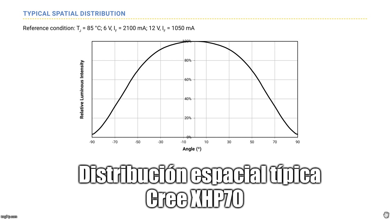
Still, the relative luminous intensity of the LED from 30deg. to 0deg. is around 90–100. From 30deg. to 90deg. it ranges from 90% down to <10. So putting a spherical reflector with a 60deg. arc in front of the LED captures the most intense light and reflects it almost straight down onto the LED (so I would hazard to postulate the efficiency goes up), whereas an RLT is capturing a light that’s, I’d say on average 50–60% of relative luminous intensity.
That said, RLT with optics are easier to implement; however getting a Wavien collar is not so easy. I’ve made a few for experimenting however. I think having a downward-facing spherical reflector has some merit still; even though it takes more tuning, it is a relatively easy mod, and in one wished, precision spherical reflectors can be easily obtained from Edmund Optics or ThorLabs… Using the GT70 as an example - even if I could get only an 11% gain - can you think of any other mod I can do that I can gain 11% and still have money left over for gas and food?
According to what I can infer from a typical spatial distribution graph, the integral of the first 30° half angle cone has nearly the same surface (≈14,6 squares) as the remaining 60° half angles (2 × ≈7,5 squares = 15 squares). To me this means the first 30° half angle cone (60° frontal cone) delivers 14,6/29,6 lumens = ≈49,324% of the total output. As I see it right now, of course.
Edit: Had a very quick read at Lambert's cosine law @ Wikipedia, suffice to say there's a lot there which is out of my league but still, the first half 30° angle looks to be ⅓ of the output and the remaining 60°, ⅔ LoL. :-D
I think it’s no accident that many parabolic reflectors for flashlights are designed such that the diameter of the reflector is roughly equal to the distance from reflector edge to the focal point. Because that would describe exactly a 30° half angle…
Yeah you need to take into account that the LED emits in a hemisphere, so even though angles close to 0 are more intense, the circumference of the circle at that angle is small.
Luminous flux depends not only on intensity but on intensity and area, which you probably found out when reading about Lambertian distribution.
Here’s some more info:
The graph with the lobes shows that at 0 degrees there are 0 lumens emitted, because the area is 0 even though intensity is max.
Also at 90 degrees there are 0 lumens because the intensity is 0 while area is max.
You need to take the area integral of this lobe graph, not just the spatial distribution that is on LED datasheets.
Read my post above, you need to take into account area, not just intensity.
Think about measuring the lux from an LED with the luxmeter at the end of a 1m long stick.
When you move around the hemisphere there is a lot more places the luxmeter can be when you’re near 90 degrees.
When the luxmeter is right in front of the LED, there’s only one spot.
Well, the lux meter can be 30deg. to either side of the central axis of the LED and still read 90% luminous intensity of dead center. I found a calculator online and found the surface area of a parabolic reflector for a front-facing LED whose diameter is the approximately the same as the distance from opening to focal point about four times that of the surface area of the opening. But even though the surface area is four times as large, the light intensity I would estimate to be about 2/3 that of the light emitted from a 30deg. to 0. And the efficacy of an electroformed parabolic reflector surface with rhodium coating is around 90%; I’m sure the cast, machined, and polished/coated surface of say a BLF GT to be slightly less. So maybe the ratio of light from the reflector versus light directly from 0-30deg. is more like 2:1 rather than 3:1.
But the reason for using these emitters is to effect a longer throw, not to put the light on an integrating sphere to get a lux reading. Your very own OptoFire uses that 30deg. half angle since that’s the aperture size of the RLT you used,. And the lens is approximately the same size as the reflector on the GT - yet it throws farther than a Black Flat installed in a GT with a reflector - despite the GT’s reflector having over four times the surface area of the RLT collar you used. A collar which you noted is about 33% efficient at collecting light from 30deg - 90deg. So using your theory a larger collar (with the same aperture angle) would be more efficient - but I don’t think so, because any errors on the surface would be greatly magnified dur the distance of the reflector from the LES. But for a larger emitter it may be beneficial.
LouieAtienza, I think one concept you are missing is that of luminance. This is a measure of the surface brightness (of the LED) and it is important in the determination of beam intensity or throw (intensity in cd is equal to luminance times apparent reflector area). The luminance of LEDs does not vary with angle; the reason the intensity goes down as you go to the side of the LED is because the apparent area decreases. See here for some explanation.
The intensity of a flashlight depends on two things, the emitter’s luminance (cd/mm^2) and the front area of the optic.
Just ignore reflectivity for now, to simplify things.
The luminous flux output of a flashlight depends on the angle of light collection, because the angle tells us both the area on the hemisphere as well as the intensity.
Try playing around with these calculators, you might see how things work when you adjust the value sliders: