I think the real ones have round pads on the wires. Your picture looks like it has square pads.
I’m not well versed either, but I’ve heard multiple people say the D10 led is a imitation unit. I would assume this also applies to the D25. It’s one of the reasons they can sell it so cheaply.
No, I’m not sure if the XM-L2s are authentic. Since the overall performance of this light is rather low it will not matter to me, though.
Yes, you‘re right. It’s about how we define a „driver“. IMHO, putting two wires and some resistors in between onto an LED is not what I really call an actual „driver“. Maybe I became too spoiled already.
I don’t mean to argue about that but one thing is for sure. Those fins inside the battery tube work as a thermal conductor between the hot area underneath the LEDs and the battery, deliberately or not.
Have you read this thread? You know this is a FET driver, right? It’s got two FET’s so I assume it’s a 2 channel driver. The big resistors your referring to are to simply limit the maximum current. So this driver is just as complicated as some of the other 2 channel FET drivers such as the one in the Q8.
The MCU and UI are not as advanced as the Q8’s Atiny 85 and NarsilM, but the basic driver design is similar.
Just wanted to add that I have the D25 and I love it. I have several headlamps and this one is by far my favorite just due to the weight and usability (Simple). Seems to hold position well and the brightness levels are good for me. I am thinking of getting the D10 just to see how well it works. Also it’s inexpensive which makes it a great buy.
Thanks, I see the FET’s share their inputs and outputs. I should have looked closer. :person_facepalming: I wonder why they used 2 FETs when one should do?
So not quite as complicated as a 2 channel. I guess this makes it difficult to get really low moonlight levels.
On the plus side there is no viable PWM as far as I can see and it has low voltage protection. Two things the old RJ02 suffered from.
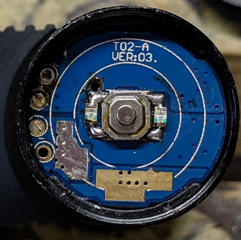
Here is a photo of the latest driver (with original MCU still soldered) from a D10 I recently purchased. This particular D10 uses the same driver version as the D25 I have. The only differences being the current limiting resistors used (1 vs 0.68 Ohms)
It would seem that the circuit and MCU difference are as a result of the headlamp release versions (ver:01 vs ver:03) rather than the headlamp model (D25 vs D10) itself.
The good news, as far as I can tell gChart’s MCU RampingIOS upgrade works fine with this D10! The bad news, there’s no way of telling externally whether a given D10 (or perhaps even D25) will work with a new MCU.
FWIW, both of the headlamps that worked with the MCU upgrade (T02-A VER:03) were purchased within the past 2-months.
Edit: The D10 with ver:03 driver that works with the gChart MCU upgrade was from the Official Boruit Store on AE.
Interesting! Thanks for the update. And glad the MCU swap is working well for you
So if it’s just a matter of driver versions and not D10 vs D25, that does make things a bit less predictable. But on the plus side, the driver is labeled where you can see it by just removing the switch cover. No need for a full tear down to find out which version you’ve got. Also worth noting, Flail’s “VER: 01” also seems to have physical debounce resistor+capacitor on the switch side. They must have eliminated that (using firmware debouncing?) in later versions.
Edit: link to where you got your D10? I know there’s plenty around, but it might be handy to know who is selling one with the newer driver.
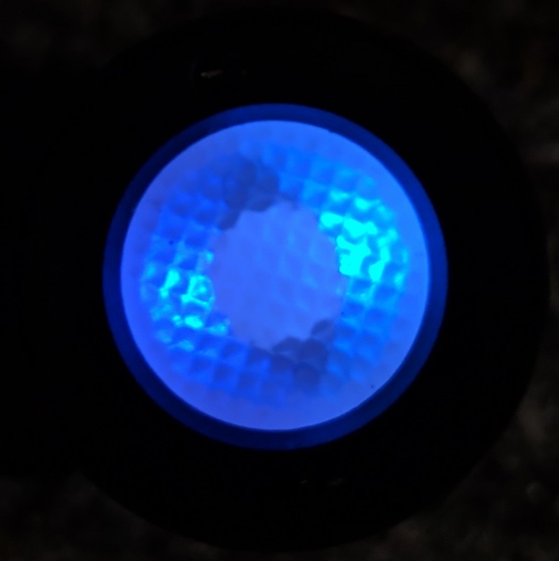
After chatting with pc_light a bit about this idea, I added switch LEDs to the D25 tonight… quick and dirty style.
The switch detection pin is pulled high at the MCU using the internal ~35 kOhm pull-up resistor (at least on my transplanted attiny412). So… I just piggy-backed that and stretched 0805 LEDs across each side of the tactile switch.
At first I tried green LEDs, but it acted like the switch was constantly being pressed, which I was concerned might happen. I think the vF of the green was low enough that the MCU was detecting the ground. I switched to blue LEDs and voila! It’s currently acting like it should. Who’s to say if it has any long term effects.
PS - stretching the solder to the 0805’s was tedious. If you have slightly larger ones available (1206?) you might try those.
PPS - the clear tailcap I used is 14x6mm, item #S024947 at Kaidomain.
Its a pity.
Yesterday I wanted to solder the Attiny from gchart. But I have Rev1 and it didn’t work.
Once I connect the battery it switches on at low level. After (not while) I pressed the switch it dimms down to lowes mode. And there is no way to make it brighter or switch it off.
i’m glad i found this thread, i have several d10s and d25s, i know this thread is mostly about modding the driver, d25 seems to me is completely out of focus, i removed reflectors, and installed a poly window instead, turning it into a mule, works great, would be better if it was not so blue, but i can live with it, i think d10 is much better light, focuses right, does not heat up as much, needs no thermal regulation, with stock driver, and you can easy replace a led… but i have a question about the bracket itself, i lost mine, (actually i did not, my cat chewed it up) i tried one from ZL and skilhunt, the light can be forced it, but they flex, you can’t turn it so it stays in that position , not without 1 hand holding a bracket and another twisting the light, and they have no ability for light to be removed in half a second, as original does. anyone knows where to get spare? i’d 3d print one, if i could design a stl, i can adjust an stl file, but can’t make one from scratch. a can do a blueprint on paper easy.