After reading the excellent review of various diodes (etc.) for measuring PWM by Terry Oregon:
I decided to see if I could get hold of the OSRAM BPW34S
I found this on Amazon:
https://www.amazon.com/WINGONEER®-BPW34-Silicon-Photodiode-DIP-2/dp/B07HBW4PJ6/ref=sr_1_1?keywords=BPW34S&qid=1554239121&s=gateway&sr=8-1
Which is currently unavailable (Hruumph!)

5 of them for $10 for a BPW34 (no S on the end – S for surface mount?). No need to wait for China, hopefully they would be similar to the one tested.
The envelope arrived and I thought it was empty. Inside was a second envelope with the BPW34(s). No documentation at all.
Geeze these things are small!
I had been using a cheap solar cell to look at PWM

At about $3, this along with some sort of oscilloscope will give you a look at what the light is doing PWM wise.
Anyhow – I hooked it up as per Terry’s example. Terry thanks for the shot telling us which is the negative side.
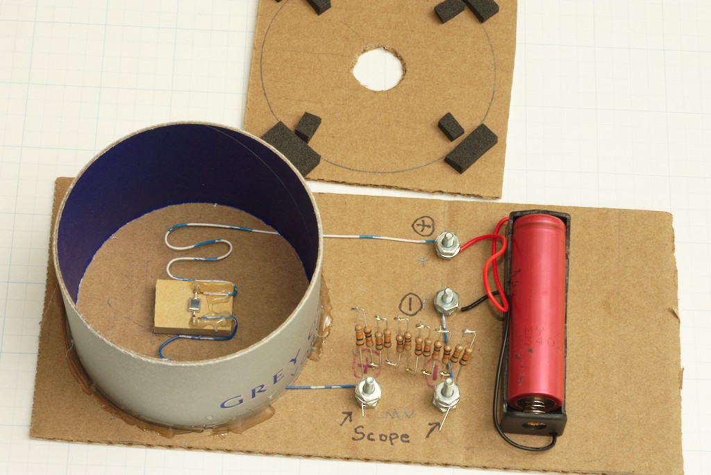
I built this setup to test PWM
A tube to hold the sensor, a battery holder, and a spot to hook the scope across the resistor array. With hot glue to hold it all (naturally).
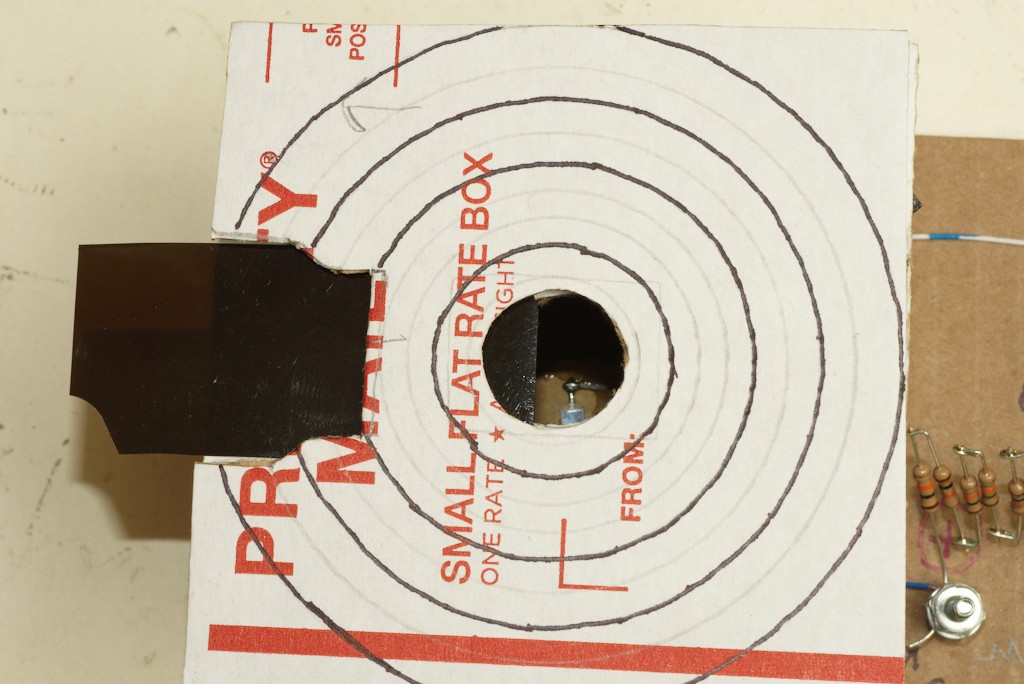
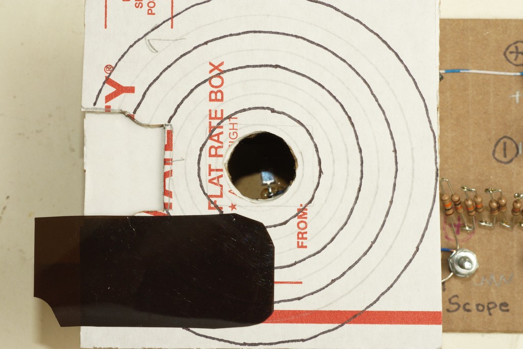
Later I added a lid to hold a filter.
Be sure to put the scope leads on the correct way or you will get a very funny looking output. I had the invert button pushed on the scope and was mighty confused until I did a dual trace with an overhead light.
I found I needed at least 5 10K resistors to get a big enough voltage to see a trace from the overhead florescent lights in my office using my old BK scope. I guess I’m losing some rise time with this setup. If I built this again I might use a POT instead like Terry.
How’s it look?
Take a look at the picture of the florescent lights in my office.
The top trace is from a cheap solar cell I have been using to look at PWM.
The bottom trace is using the BPW34. Quite a resolution difference!

The second picture is a pair of traces from a flashlight. See how the solar cell has a slow V drop compared to the BPW34.

I do notice a negative (ring?) on the test setup. Anybody have a clue what may be going on?
Perhaps my lights just suck and that results in a negative voltage.
It tried it with a few flashlights. I was getting odd looking waveforms. I believe the lights were so bright the signal was clipping and not showing anything above the full pass through voltage.
So I built a lid to hold the flashlight that has a compartment with slide in filters to cut the light in the chamber to something the system can handle. The filters are real high tech. I cut them out of a set of those dark film glasses you get at the eye doc to make the trip home after you get dilated.
Now that I’ve got this nifty toy, it’s time to upgrade my ancient oscilloscope to something that can do a screen capture and give me a frequency (without me having to think too much (which is always a good thing)).
Any of you have any positive experience with USB scopes? Not looking to spend a lot since this will be basically a toy. I’ve heard good things about the PICO scopes being better supported than the no-name brands.
Since I got 5 in the package, I’ll keep an extra (just in case) and as a thank you to you tech savvy BLFers, I’d like to give away the other three.
Let me know and send me a PM with a (US only please) mailing address and I’ll mail the BPW34 and some resistors for you to play with.
All the best,
Jeff


