In my experience with XL4015 CC/CV buck modules they can dial down as much as you want Lightbringer, firefly levels or even lower. It is very important to use logarithmic taper potentiometers for this because we're adjusting perceived brightness out of drive current.
When (if?) you get yours, lemme know if it’s true buck/boost. The 2577, well, I’ve only seen in plain boost config with a single inductor, and you’d need an actual transformer for buck/boost. Or, you end up with negative output from positive input (and both these grounds are in common and imply positive/positive).
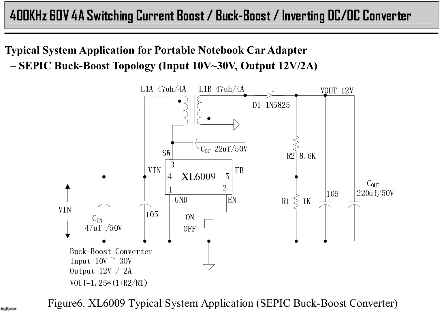
And if you look at that .pdf, all the sample circuits have 12V-16V input for 18V output. And the only SEPIC circuits in there use transformers, not plain inductors.
The converter's topology looks like this one found in the manual, so I think it's buck boost no doubt.
By the way, a transformer basically are two coupled coils. An XL6009 can handle its coil pair for it to operate like variable transformer, or so I think.
Unno, maybe they’ve got some trick circuit that lets it be a buck/boost, but…
Like I said, when (if) I get mine, I’ll put it to the test. Would actually be nice if it were a true b-b. Lots lots lots more flexible for the stuff I could do with it.
SEPIC doesn’t require coupling between the coils, although you can often reduce the space taken up by the coils if they are coupled (which increases their effective inductance) and thereby build a smaller conversion module.
See here:
and scroll down to “Using a Transformer”.
As usual with inexpensive Chinese modules, the simplest way to find out is to buy one and see what it does
My modules were shipped already. It is a good thing that Correos (main Spanish postal operator by far) reached an agreement with Sinotrans Limited a few years ago, I can choose Ali Saver or Ali Standard and the majority of times this means Sinotrans - Correos which comes home quite fast.
I'll be able to take a quick peek at the modules next week. ;-)
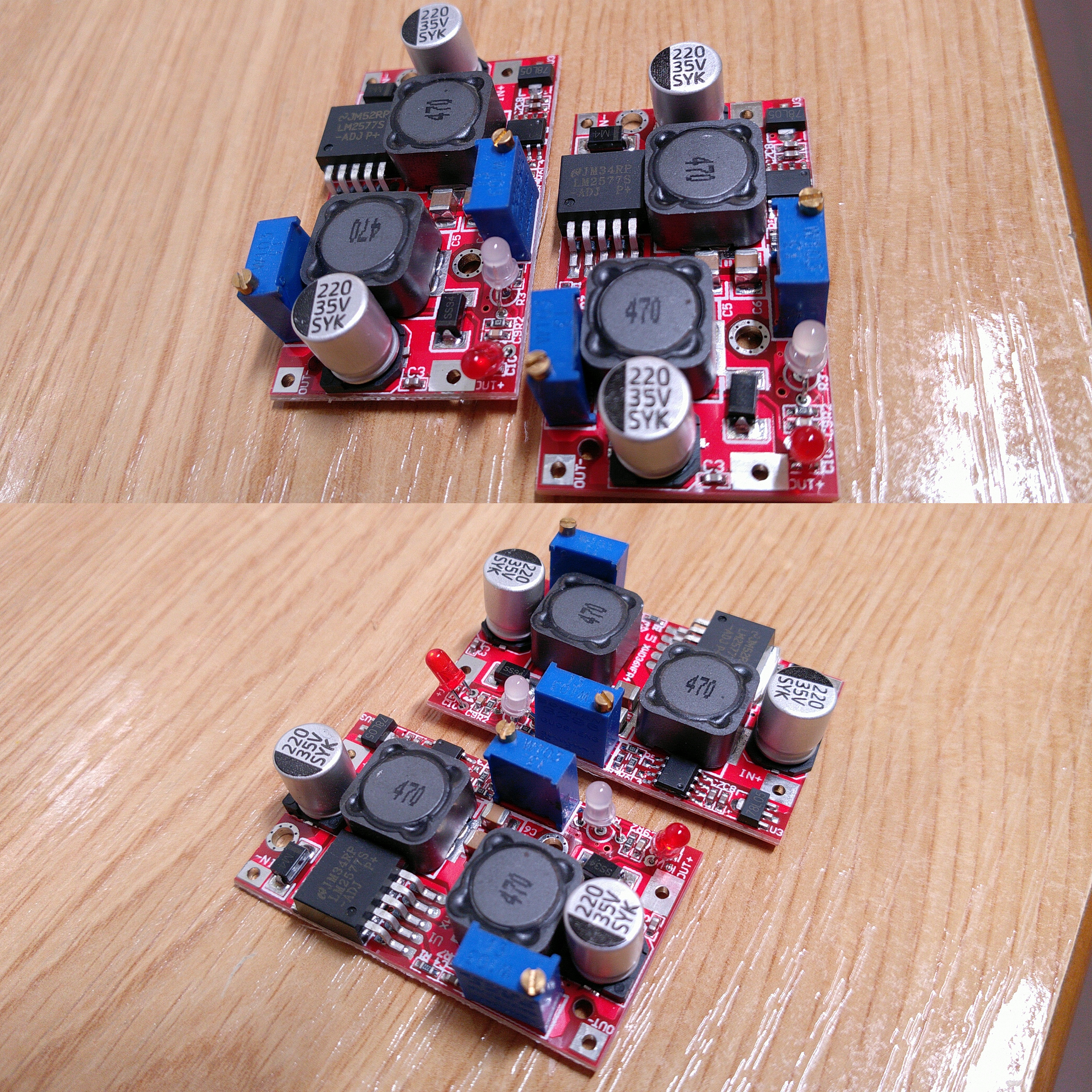
So it matches the title well, it is based on an LM2577-ADJ integrated circuit. The board layout is a little bit different, namely at the switcher's leads for obvious reasons. Whether it is buck boost or not it a mistery is to me until I try it with my PSU, but it should.
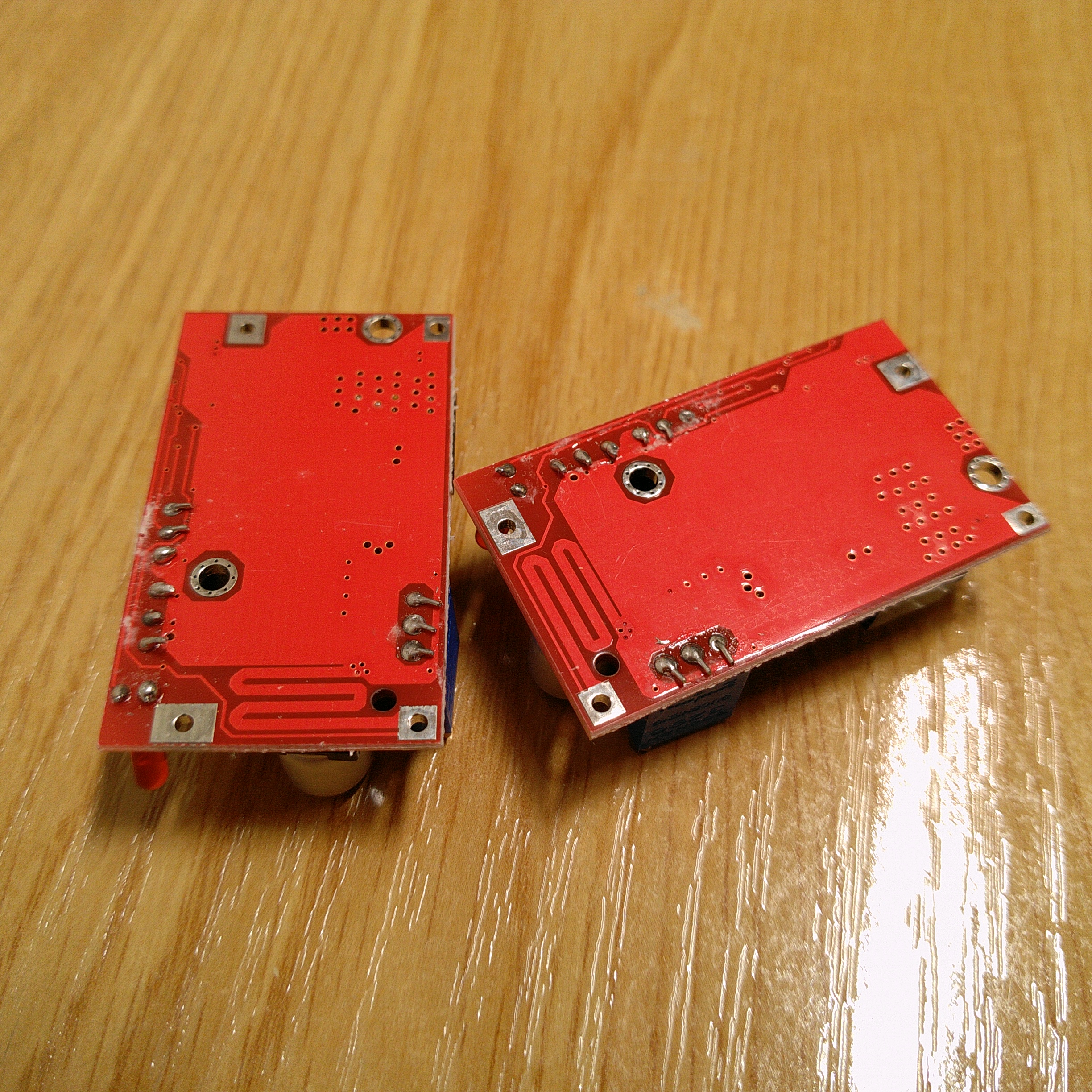
Underside pictures. Notice the current sense track, right at the voltage trimpot's feet.
I've quick tested one. Fed with 7.24V from my PSU I've been able to adjust the output all the way up to 26.9V, and all the way down to 1.237V according to my Bside/Zotek ZT102 multimeter. Voltage adjustment is sort of logarithmic, took a lot of turns down from 3V. Hence, whoever devised this module knows something. ;-)
The unmarked chip next to the 78L05 regulator must be an LF351 or LM351 amplifier for the current sense thing. Compared to other modules this thing is using a quite low resistance current sense track, like 10mΩ or so.
That one has end current percentage turn lamp setting and two switcher ICs: LM2577S + LM2596S. Besides this, the above board is marked as XW036FR4, whereas the one discussed here is marked as XW036NFR4 (check it in my #28 reply).
3rd trimpot is usually for end of charge (low current) detection adjustment
That last kind of converter theorically has a lower efficiency as it's made with a boost converter followed by a buck converter so you have to account for the two stages losses
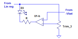
The turn signal is meant to indicate at which point the current output is lower than the given ratio, for battery charging duties namely. It is set fixed as 1/10th in the OP module.
I have an interesting question, because as I see this module it looks like it is parallelizing friendly. First of all the diode at the output makes it reverse current inmune. Next question is, is it reasonably possible to use the same control trimpots/potentiometers for two or more modules? The idea is to use common voltage and current trimpots/potentiometers, this way the modules should share load with great balance…
Nah, it’s a joke. Like the funny kind, only different.
In car manuals, they’re called “turn lamps”, not “turn signals”, just like “CHMSL” vs “3rd brake light”. So when the spex for this donk kept referring to a “turn lamp”, well…