The stair-step pattern is the button’s blinking mode in standby. It loops through a 16-step pattern which looks a bit like a slow heartbeat.
FWIW, the button has 4 modes:
off
low
high
blinking
But what makes me happy is that there are no spikes in the flat zone in the middle of the graph. That means the power use is too low to show up on the scope. It wakes up 8 times per second, so it theoretically could have six spikes in that flat zone, but it doesn’t. So the cost of waking up is indistinguishable from zero.
What it actually does during those brief wakeups is send a “EV_sleep_tick” event through the UI code, which the UI can handle however it wants. In this case, it just updates the button brightness level. Then it goes back to sleep. But this could also be used to implement a timer for a sunrise or alarm clock mode, or to otherwise do things while it’s “off”.
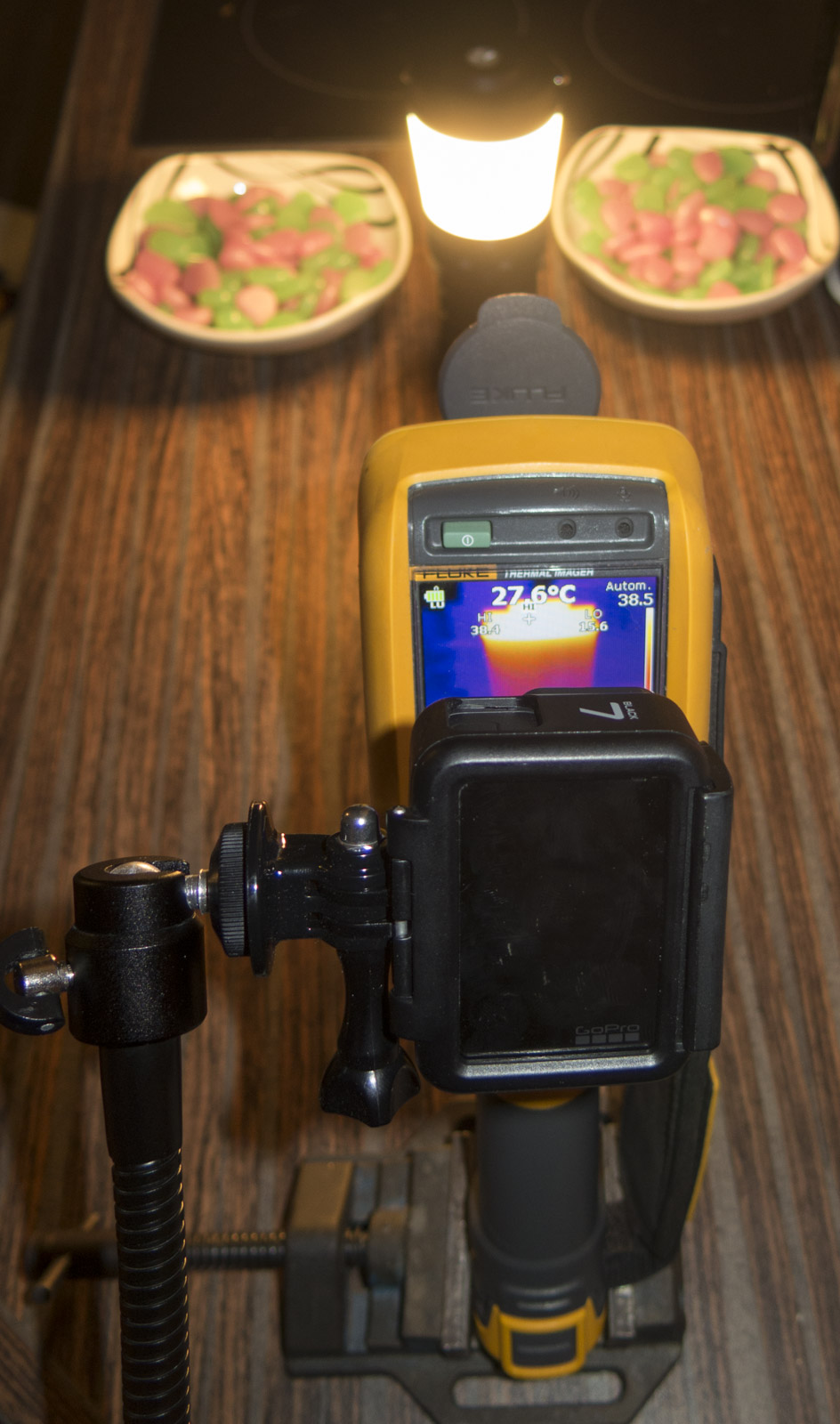
good to hear. :+1: Those are comparable temps i got from the V2 prototype before i resistored the driver back from 2.0 amps draw on maximum, mode after 15 minutes, i got a measured 58 degrees C at the top center of the lantern head with the four 4000K LH351C emitters, then at around 52 degrees with a amp load of 1.65 amps for same duration. ( though its likely this production sample will have better heat dissipation and tolerances for heat transfer from the LED MCPCB to the solid aluminum head.
Lexel, I pieced this post together with data from your post above. I know the test conditions may have been different, but I am guessing he max current you saw with the 7AMCs running was the 2.5A measurement from the video (from some tint ramping testing). Is this correct? Makes sense, 7x0.35A gets pretty close to 2.5A.
Those who don’t want such high levels can disconnect some of the 7135s, It looks like from a picture of the driver board I saw you could (if you wanted) reduce the number of 7135s to only 2. About 5 hours of run time at max with 7 7135s, and 20 hours with 2 7135s on max, assuming 4x3500mAhr batteries. Really looking forward to fooling with one of these when they go on sale. You put so many hooks in place one does not need to be a “modder” to make adjustments here.
Nice. It looks like it performs better than expected.
I thought the plan was to use 4 or 5 AMC7135 chips per channel, with solder pads available for the user to increase it up to 7 if they want. Is the plan to enable all 7 by default, or just 4 or 5?
Does this light have a better physical reverse cell protection design than the Q8 v1 had? The Q8 just had a thick brass ring with out any raised plastic on either side of it to allow only a positive battery nipple to make contact.
This lantern with its safe low current and built in charger would make a great gift for a flashlight muggle. But that Q8 battery+ brass ring design would give me reservations gifting it to someone who might put in a battery backwards.
This prototype doesn’t have a RPP (reverse polarity protection) ring inside, but maybe the production model could. As long as it’s fairly easy to remove, it should be fine.
It is perhaps not something that you would like to do when you buy a new flashlight (unless you are a flashoholic/modder, in that case no light stays untouched for more than 15 minutes), but you could glue a plastic disc on the driver yourself, filling the space inside the brass ring, just a tiny bit protruding above it. That will take care of the reverse protection.
The MCU has reverse polarity protection, the charging circuit not
I guess to play it save adding a reverse polarity protection FET to the charge circuit on final driver revision would be no harm
Easy trick, if you dont have the depth gauge part, is to stick something in the hole and measure it with the other end of the calipers.
Look at the “Taking a Step Measurement” part:
The classic mistake with the Q8 (reported more than one time) is sticking in one of the 4 batteries reversed, and there is nothing that the circuitry can do about batteries directly shorting against each other this way. With some bad smells, one or more of the bottom springs will collapse and likely break electrical contact and save you from battery destruction, but you will have solder new springs after that.