Nah, it’s a joke. Like the funny kind, only different.
In car manuals, they’re called “turn lamps”, not “turn signals”, just like “CHMSL” vs “3rd brake light”. So when the spex for this donk kept referring to a “turn lamp”, well…
That doesn’t usually work, as the converters will have very slightly different feedback voltages.
For example, if you put two in parallel, one might go to standby at 0.60V of feedback and the other might go to standby at 0.61V. What happens then is that one will stop converting before the other, so that the other ends up bearing all the load and either frying or shutting down. At that point, the first one has to bear all the load and either fries or shuts down as well.
You might get away with it if you use trimpots on each module to adjust for the different feedback voltages, in addition to your main control potentiometer, and add load-balancing power resistors in series with your module outputs, but that gets very fiddly, especially if you’re doing it for more than one control.
You can also run into problems with things like thermal effects under load making the feedback voltages drift at different rates, so you end up back where you started with one module trying to bear the entire load again.
Easier if you just buy a more powerful converter module in the first place.
The problem is that when i get it i like your kind of humor but sometimes, even if i understand the words, i miss the cultural reference to understand the pun
@maukka : i didn't know that one TY (i hope that when doing that they allow for enough hystheresis to avoid on/off/on/... cycle)
Well, I understand the reasons to prefer a single, more powerful module versus 2 or more in parallel. Anyway, and in this particular case and partly thanks to the anti-reverse output SEPIC topology, 2 or more modules can then be parallelled by properly tuning the output voltage trimpot in each of 'em to match as close as possible, then swapping their current trimpots with a dual, triple, quad, etc. potentiometer. The only concern I see is that, in my experience with cheap logarithmic dual pots, their gangs aren't finely matched, they're like 5% tolerance. This should be nothing major, though, with regards to load balancing. Or does it?
OK, now you’re into a zone where I haven’t actually tried the arrangement you’re suggesting
If you can get the module voltages to stay in alignment (the hard part), then current control deviations from multi-gang potentiometer tolerances are less likely to be a problem. The trick there will probably be to keep the maximum current setting per module at the module maximum minus the largest deviation that the potentiometer could introduce. That way, you shouldn’t overload any one module.
Although those deviations will prevent the modules sharing the loads equally when current limiting kicks in, they should settle in reasonable states. For example, let’s say you have 2 modules, each nominally bearing 50% of the load, and ±10% deviation from the multi-gang potentiometer. You could then have one module bearing 45% and the other bearing 55% in the worst case, which may eventually shorten the life of the module that runs hotter, but probably won’t cause major issues.
Once again, this is not something I’ve actually tried, so don’t rely too heavily on my thoughts here.
Having said that, you might also be able to get the current limiting to catch any overloads on modules whose voltages become misaligned, but that would add still another tolerance to factor in, which means that you’d have to set the overall current limit lower, costing you a bit more still of your total output capacity.
I’ll be interested to see how you get on with this experiment
That joke I got without effort Lightbringer, that was culture-independent enough. ;-)
Tested both my modules a few hours ago, both buck well with load and I found no need for further testing being it an LM2577. With the board oriented sideways with input at the left and output at the right, the current trimpot adjustment is counter-clockwise (right way decreasing). Didn't pay much attention to the leds but both were on (and red) when in CC mode. Left side led is bi-color, lights up green when powered on unloaded.
I have not spoken of this before but, when using these kind of converters fed from AC, what about efficiency? I mean, if we feed these off a regulated mains switching power supply the combined efficiency (mains supply efficiency times converter efficiency) does not look exactly great. Besides, when using these converter modules we do not need a constant voltage power supply, a classic unregulated AC-DC supply can do and is supper efficient (mains transformer plus bridge rectifier and capacitor). Unregulated supplies were all the rage years ago but this is not the case now so, what's the deal? I also do not see the massive and bulky AC-AC “gearbox” transformers of yesteryear in the newer supplies, they look comparatively tiny and lightweight now, did they improve that much?
Tranformer and filtering capacitors for the old type power supply work at mains frequency (50-60HZ) while the switching AC/DC PS work at much higher frequency (typical 100kHz-1MHz) so it can be a lot smaller and cheaper and i don't expect a non regulated switching PS to be much cheaper than a regulated one so we have regulated output.
To tell the Truth most of the old power supplies (at least the low power ones) where not that efficient ! The cheap transformers had a lot of loss. Do you remember those old plug mounted power supplies that were hot even with no load ?
Non regulated supplies were a thing because most of the time the regulation was on the "user" side and usually used a linear regulation that was way less efficient than any modern switching supply.
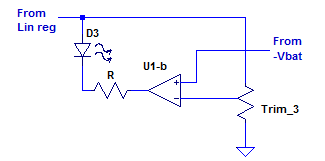
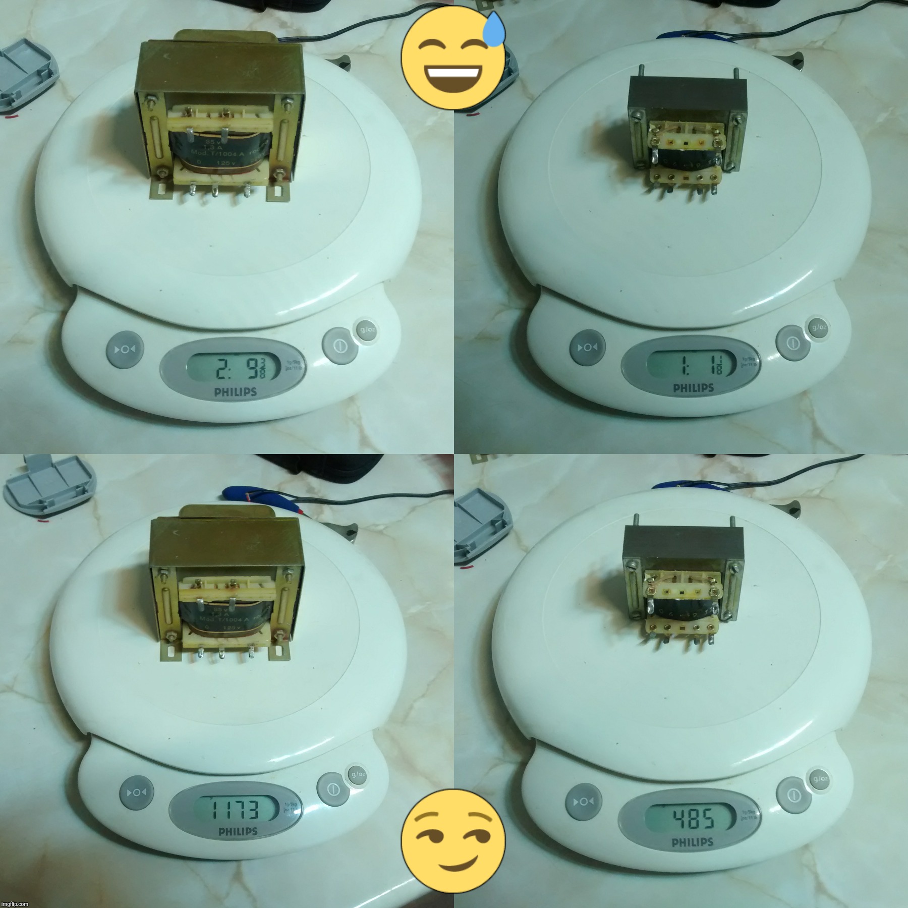
Wellp, my transformer is of decent quality I think, made a picture of a couple units I have ≈3 years ago:
The one at the right. Haven't checked if it gets warm just by being plugged, though.
You say they switch at much higher frequency, 0K. I do not usually see two transformers in power supplies (some do), one for frequency (?) and the other for voltage. Are they integrated in the same device? I mean, do I connect 230VAC 50Hz by one side and get, let's say, 12VAC 100KHz by the other side? LoL!
How are these devices called? I find it takes more effort to find relevant results now with search engines than what used to be in the past, prior to the philistine consumer market crowd internet invasion. Miss the days of the uncensored internet with pure logic search engines unhampered from spelling correction duties.
The kind of converter i am talking about is what you find in laptop brick power supply or the small mains to USB converters (and many others).
There are several ways to do that but the easiest (and somewhat durty) way is to rectify the AC mains with diodes and filter it with a 400V capacitor, then the high voltage DC is switched (Mosfet) at high frequency (100k-1MHz) and sent to a transformer whith a low voltage secondary winding, then this low voltage is rectified and filtered to give low voltage DC
The chip that control the switching usually take care of the regulation but in order to keep the low voltage DC side insulated from the mains side the feedback is done through an auxilary winding or an optocoupler
Edit : That's how you get power supplies that are able to run from 110V or 230V without any configuration switch
The size of a transformer is (roughly speaking) related to the power you want to transfer divided by the frequency so a transformer working @100kHz is many times smaller than a transformer transfering the same power @60Hz
Sorry from where i am now i can't insert pictures and i can't even read the product description in the previous link but from the picture this look like a forward converter.
If you look at the first picture in my link (top view of the converter board) you can see :
Left : this is the input LC filter (avoid to send too much HF content to the mains)
Left bottom : rectifier bridge
right of the rectifier bridge : 100uF/400V capacitor (high voltage DC filtering)
on top of the capacitor : Switching mos with heatsink
right of mos : controller chip, the diodes and capacitor between the transformer and the controller might be for powering the controller from an auxiliary winding of the transformer after start
transformer : as you can see the size is not that big for a 180W converter
right of the controller : the long 4 pins chip is probably an optocoupler for the insulated feedback
right of the transformer : 2 diodes on the same heatsink (rectifier diode and freewheeling diode)
the black thing with heatshrink is a vertical inductor
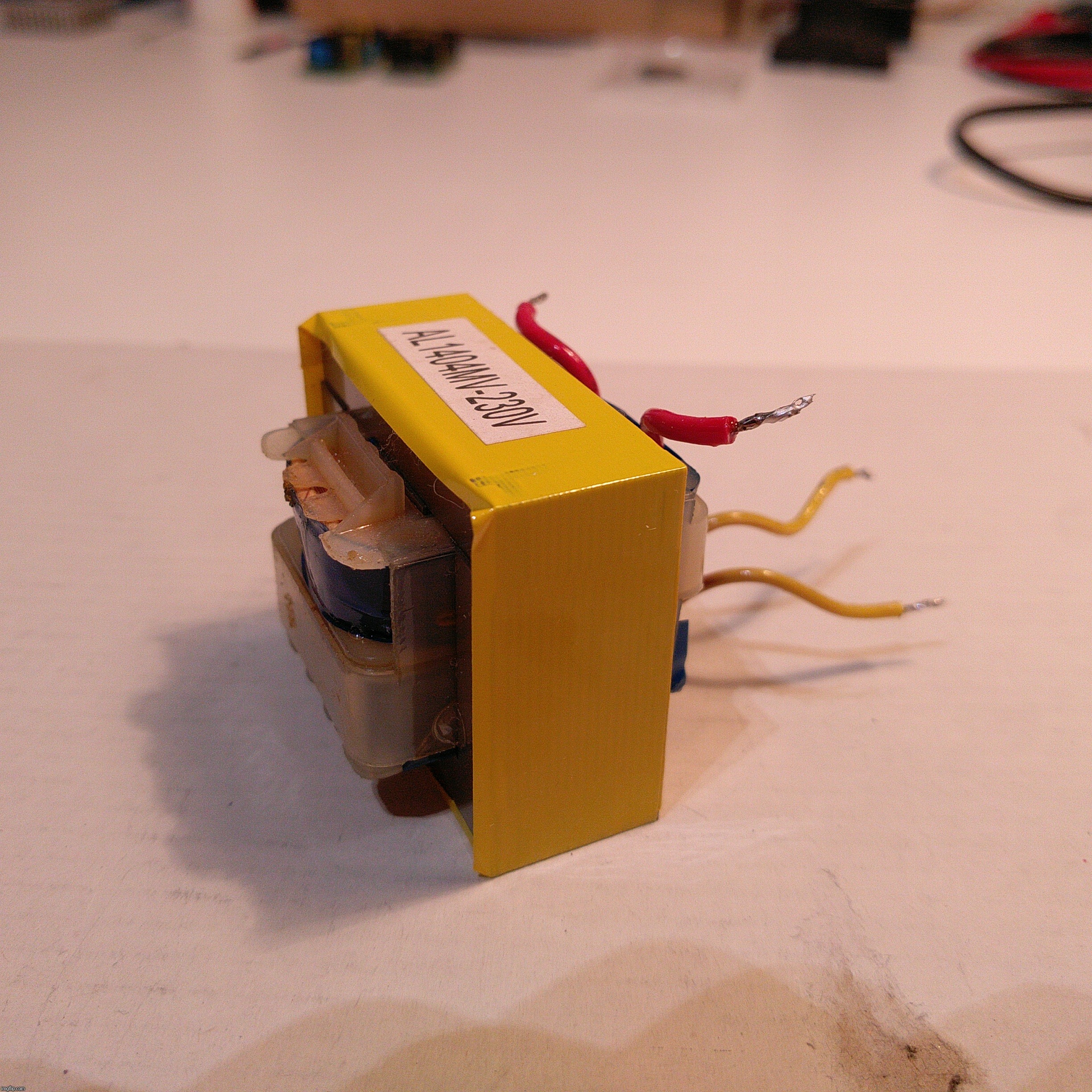
That supply you linked looks like a bigger version of these two I recently bought:
I bought these from CZB6721960 Store, the one at the left is a 12V 0.5A rated unit while the right one is 5V 1A. They have integrated bridge rectifiers underneath at the input. Isolation distance looks adequate at 4.5 - 5mm. The seller has cheaper supplies but bought these because of the input coil (LC filter?), the safety capacitors and overall construction.
I am right now testing my old transformer for standby power usage, left it plugged a while ago and will measure how hot it gets but, now that I think of it, I could measure its unloaded input current with my O:) hobby multimeter. Its gear ratio is ≈16.823/1.
Actually, transformer + bridge + caps is a nasty setup. Lousy lousy lousy power-factor. It’s essentially zero load except for huge current-spikes at the peaks of the ac voltage.
Even bridge + caps right off the mains does the same thing.
So tricks to correct PF are done with coils (“transformers”) before anything else, but I’m not terribly familiar with how it’s done. It just attempts to “smear” the current draw over most of the cycle vs only at the peaks.
Wellp, the transformer got slightly warm to my fingers. Then I measured its no load input current by unsoldering one of its leads and setting my multimeter in its 600mA shunt scale connected in the middle with crocodile :-D clips at ≈13.23mA. At last, measured mains voltage at ≈235.7Vac, non simultaneously of course. Wow! If math is correct that is pretty leeching. O:)
I guess this means I am better served with a modern AC power supply. My goal was to obtain infinite variable brightness adjustment without having to resort to two “full” power supplies, but I guess there are no inexpensive DIY AC/DC supplies where I can stick a logarithmic potentiomenter for current control. Or are there?
I have a couple 95W HP laptop bricks, same type, one nearly brand new and the other with 11 years of tough service. I wonder how efficient they are versus one of those newer supplies. Far overrated for up to 25W in any case.
This other unit was recycled from an old Bosch drill battery charger which I converted to li-ion. Just measured its unloaded current consumption and the meter said 0 (!). 0K, not exactly, I rotated the switch between the A and mA ranges a few rounds and each time it got in the mA range I could briefly see a ≈0.2mA figure, then 0. This is a much newer unit and definitively this is a keeper for some DIY project.
Found another center tapped transformer ripped from an old amplified speaker set, at ≈239Vac input the @#$% was sucking ≈53.6mA of input current. Wow ≈12.8W of no-load input power, who wants it as shooting target? LoL!