Or
“How to Kill Your Sound Card in 3 Easy Steps”
This is a branch off these threads:
Terry Oregon (Long) Various sensors for measuring PWM
My post about building a sensor based on Terry’s design
ToyKeeper’s post about seeing PWM in the shower
(err… make that seeing PWM in shower spray photo)
A quick PWM overview (thought we might need this)
PWM (Pulse Wave Modulation) is a commonly used method of controlling the brightness of an LED. Basically the LED is turned on and off at a specific brightness. Hopefully at a frequency fast enough to prevent our perceiving a flicker when it is in use. To obtain different lumen outputs the LED is in the on position for a longer period during the on-off PWM cycle. Looking at the output of the light looks like a square wave. There are several posts about understanding PWM if further info is needed.
There are various methods to discern if a light is using PWM to control brightness. On a low setting lights with slow PWM are easily detected by waving fingers in the beam. You’ll see stop action like image instead of a smooth motion. Panning the light around or moving your eyes also gives this effect.
Lights with a higher frequency PWM are hard to detect. ToyKeeper’s post shows how to use a photo of falling water or a moving white card to detect PWM.
PWM occurs in the audio spectrum (as far as I know). So it occurred to me to try to use audio analysis software to measure the frequency. For this first go round I used (REW) RoonEQ Wizard found here:
Any audio geek needs to play with this. You don’t need anything special. Most OSs supported and you’ll need a Java runtime.
Did I mention? It’s free!
There is a bit of a learning curve to this, but there are plenty of forums and youtube videos on how to get started.
I put it on an old PC running Linux. I didn’t want to risk something newer in case I had an “Oh-No!” second and zapped the sound card.
Lights Volts Sound Lights
First I tried something simple and safe.
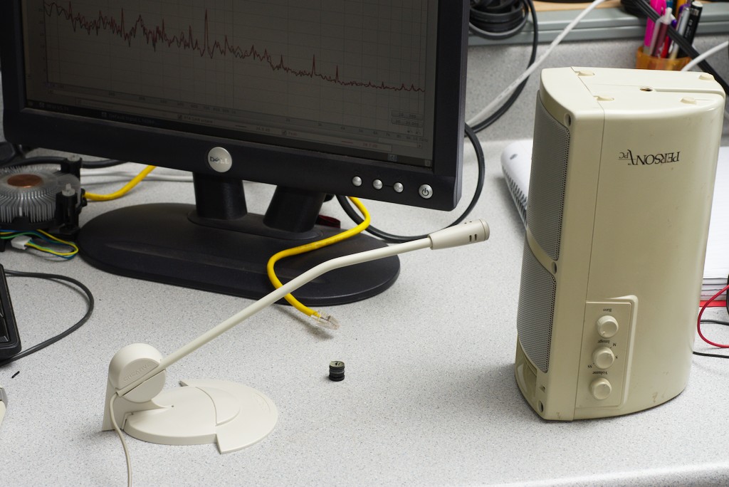
I hooked a PV cell to the input of an old powered computer speaker. Shining a light at the cell made the speaker sing at the PWM frequency. To try to get a measurement, I stuck a mic in front of the speaker and used that as an input to REW.
My office is RF central and noisy. I could see some signal above the noise, but unless I knew what I was looking for, I’d be hard pressed to make a confident number. I do think this would work better at night in a quiet environment.
Lights Volts PUFF
Warning Warning Danger Will Robinson
This next section uses an input method that connects a voltage source directly to the sound card.
This is not wise unless you are VERY sure of the voltages involved.
MIC input 50mV. LINE Input 1 Volt. Suggested max voltages.
I will be making a safe version in a later post.
If you are going to try a naked input, I suggest getting an external USB sound card.
More on this in the next article.
Here’s what I built
I could have connected the PV cell directly to an audio cable, but I wanted a bit more flexibility if I wanted to try different sensors.

So…
I ripped the audio I/O off an old motherboard and got to the pinouts. I figured out what went where and added a connector from a dead amp so I could swap stuff out easier.

I needed to block out more background light so I put the PV cell in a tube and used the lid from my previous experiment (in my thread mentioned above).
I needed to use the filters to keep the voltages low enough to prevent toasting my sound card.

With typical room lighting this cell puts out about .2 to 1 volts. Just about right for line level audio. Throwing caution to the wind I plugged this straight into the line input of the sound card.
Ahh, much better than the sound version.
This is a shot of the office lights.
The horizontal scale is logarithmic frequency and the vertical scale is decibels (which is also logarithmic in itself).

A strong peak at 120Hz from the overhead florescent lights with all sorts of harmonics running up the Freq. band.
Here is a shot with the lights off

Still some remnant noise.
Let there be PWM Light
Here is the rogues gallery of lights
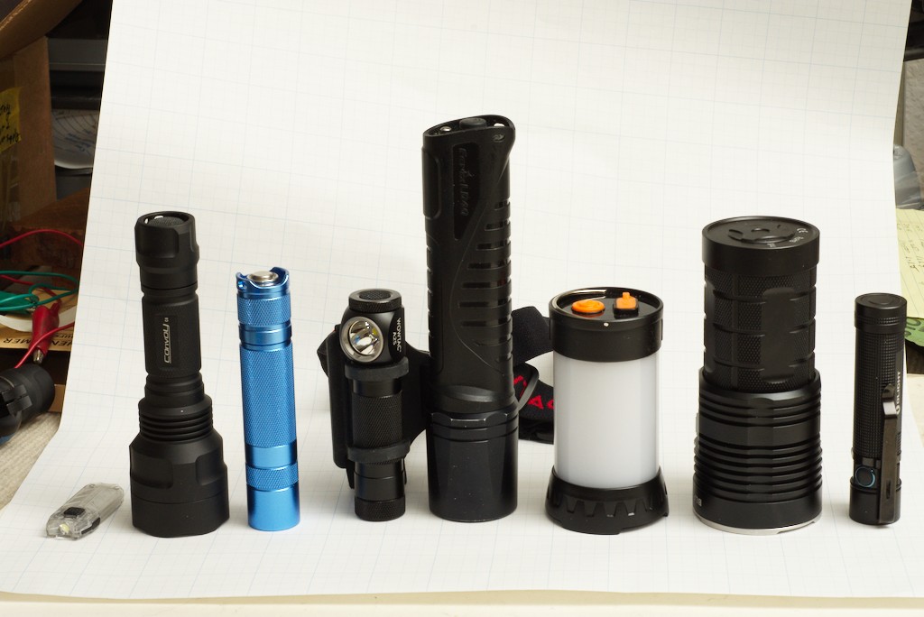
Nitecore TUBE, Convoy C8, Convoy S2+, WOWTAC A2S, Fenix LD40, The Camp Lamp, BLF Q8, and an Olight that didn’t make the show.
Nitecore TUBE light on low

You can see a strong peak at 500Hz with harmonics out the wazoo running up the frequency band.
Nitecore TUBE in Ramping

See the strong peak at 3KHz. When the TUBE ramps it changes it’s fundamental PWM frequency.
C8 with Guppydrv – Medium
I have the Guppydrv in mode (18?), five stepped modes (levels).

Wow, 16.5KHz, This Guppy/puppy is singing.
Many of us old farts can no longer hear that high.
Unless this was really loud, plugging this one into a speaker might not be recognized as having PWM.
Convoy S2+ Standard 3 mode driver
Everyone has one of these – right?
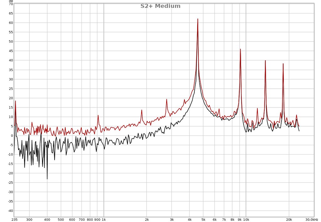
The main peak is at 4.5KHz
WOWTAC A2S Headlamp - Moonlight

I don’t see any PWM frequency. So I guess it’s just running the LED at a low voltage (more tests in the future article to confirm this).
WOWTAC A2S Low

Here we see a 15KHz PWM
BLF Q8 - Moonlight
This, BTY, is the light that started all this mania
(And I blame all of you!)

BLF Q8 - Ramping
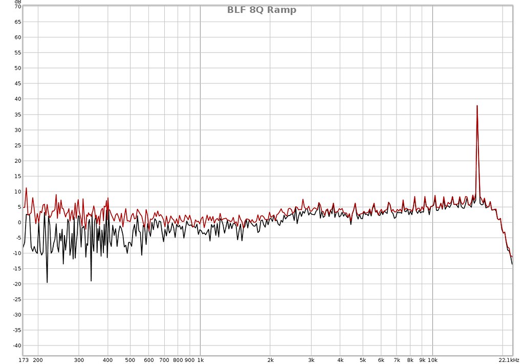
Looks like both are controlled by PWM
Fenix LD40 – Low

Here’s a fine older flashlight. You see any frequency that stands out? Me neither. I believe this light is controlled the old fashioned way. Less volts - Less photons.
And the worst PWM (So far)

100Hz! Really?
Someone in China needs to be forced to work under this as a penance.
Conclusions
Using audio spectrum software or anything else that can define a pitch can be used to measure PWM frequency in flashlights. What’s missing is getting a look at the waveform to see what is going on during the PWM cycle. I’ll address this in the next article.
Once again, be VERY careful doing this with a direct input into a sound card.
Smoke may occur.
I was using the LINE level sound card input.
And I was using 3-4 heavy filters to drop the voltage enough to keep things safe when measuring lights on low and medium brightness.
I’ll post a design for a safe input circuit in the next in this series.
And just when you thought you’ve had enough of my ramblings….
Coming soon to a BLF post in your neighborhood.
A Soundcard Oscilloscope:

