New “smart” tailcap today. This one is mini for AA sized lights. Swapped out a friend’s Booster Tail for this one since he always uses his Sofirn SF14 with li-ions (with AA/NiMH the flashlight will still work of course, just not the tailcap now). It has 6 LEDs uses them to display battery status.
First battery in the video was at 4.07 V, the second was at 3.55 V.
For my Convoy M1 with L4P driver, yes. Pretty straightforward, just 2 pin to solder between your board and the omten switch and that’s it !
For the Tool AA, unfortunately I didn’t think about it before but I use a Biscotti 5*7135 driver… so the bleeder resistor is tricky to define. I used a 332 (3,3Kohms) but now it’s “next mode” memory…
I have to try a smaller value maybe ? Anyway, I put the tailcap in the lathe at work to accommodate a 14mm clear tailcap
I pretty much always just use a ~840 Ohm bleeder for Bicotti-type drivers. As long as you’re not using an OTC, they usually don’t seem too picky (unless you’ve got the FX-12 type… I’ve never had good luck with those)
I'd love something like this on some of my lights. It's often bothered me on my simpler lights that I don't have built-in charge indication. My ideal operation would probably be to tell me battery voltage when I first turn on the light... possibly even stay lit during use (and live-update the display periodically). I'm worried I'd have trouble counting the pixels, which makes me lean towards someone else's earlier suggestion of using like two red, two yellow, and four green LEDs. So 100% would be all of them, 50% just the red and yellow, and 25% just the red.
Because of how illuminated tailcaps work, they only light up while the flashlight is off. Aside from that, what you’re proposing is very easy with the existing hardware. I’d just need to play around with balancing the colors and tweak the code a little bit. I usually don’t get too much into color mixing due to color blindness, but I could definitely make one for someone else… and have the wife verify that I got the colors right. If you’re interested in something like that, hit me up on PM.
That is really kind of the only thing I ended up liking about my Nitecore EC23. Because I had to always lock it out (or else it comes on in my pocket, virtually guaranteed), when I went to use it I'd get the battery voltage blinked out the second I tightened the tailcap. I'd love to have my lights tell me their battery status the second I turn them on, in a non-disruptive way. The best way, to me, seems to be to use switch lights. Since all my lights that I care about will start in low or moonlight, I wouldn't mind checking a light by briefly turning it on. For bonus points, the dumb-switch lights would still have absolutely 0 standby drain still, and I wouldn't have to worry about bleeder resistors on the drivers.
But yes, I can see what you mean from the design standpoint. There'd have to be another voltage drop in series with the main LED/driver, and that just wouldn't work. Alternately, there'd have to be a second current path, which leads to the FW3A all over again. Obviously this works fine with E-switch stuff because there's current already there, and some manufacturers already do something like it.
And no, I can't PM you, you're up to far too many awesome things. I'd have to go sell plasma or something. It seems like half the new interesting things I stumble across here have you involved :P
Still, the standby drain you mentioned is low enough, even at 0.35mA that's 1800 hours to drain my 650mAh Olight 16340s. None of my small lights have space for this in the switch anyway, so it would be going on a 3000/3500mAh 18650, which is around a year to drain. And that was the overly high standby drain you mentioned, with the wrong resistors.
Ugh, you monster. I'll have to remember to PM you in a few months. I just took two cats to the vet, and bought a new chair.
I have build colorful tailcaps, but they know only 3 stages
LVP -> OFF
LOW -> red
Normal -> all LEDs lit, red off
a battery indicator on light os can be realized with Aux LED board
I have made a solo board that has the 3 stages and an external switch board with different LED channels same as my Aux boards
its untested so far but should work in most e-switch lights
the base board is 14mm diameter and only 3mm tall
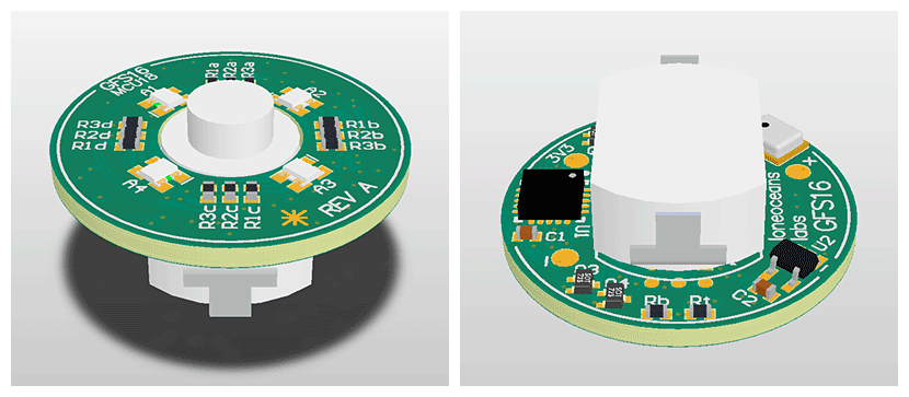
Hi everyone, great to see the development work here on taillight switches! Here's one I made about a year ago but haven't had time to write much about it. It's nothing special, just another LED taillight board. I designed it a while back with my GFS16 tailswitch system, built a few, but haven't completed writing all the features of it yet in firmware.
Here's how it looks like. I'll try to find a photo of it when I'm not traveling. On board there's a micro, as well as a battery measurement system.
Some other interesting features including a microphone (initially I designed this to be a 'clap' sensor, so you can change modes on the effects of the tailcap, as well as four RGB LEDs). So for example, you could have the micro do fun things like make the LEDs breathe, do a rainbow fading pattern, or just show the battery voltage in terms of colour. Or you could use it for other things as well, such as dancing LEDs to external music. Though in reality the most practical is to have the micro do some clever pattern on the LEDs then go to sleep to save battery power.
I was wondering what that component was until I read your description (the microphone); interesting idea indeed.
I’m just now learning about these small RGB LEDs. Before them, all I had seen are the 5050 type. I may have to make a version of my “smart” (MCU-driven) tailcaps with some of those. Where did you source yours from?
What did you do for battery management? I was just using the internal 2.5V VREF in the Attiny416 for mine.
For battery voltage measurement, I simply use a regular LDO to generate a reference rail (and power the micro). The regular ADC on the micro (I use a ATtiny841, again arbitrary choice) seems good enough. By controlling each group-anode and each group-cathode, the micro has full control of each of the 12 LEDs using 7 pins.
Finally got a chance to put more smart tailcaps together. I got request for a dual-color one… I think I like it!
Note: the tailcap does periodically re-check voltage on it’s own, but I have it set for hourly checks. So for testing purposes, I just disconnected/reconnect between voltage changes.
I just wish I had more time. I have so many ideas and designs rolling around in my head… not to mention all of the partial builds and custom drivers awaiting tweaked firmware. Slowly chipping away one 2AM night at a time.
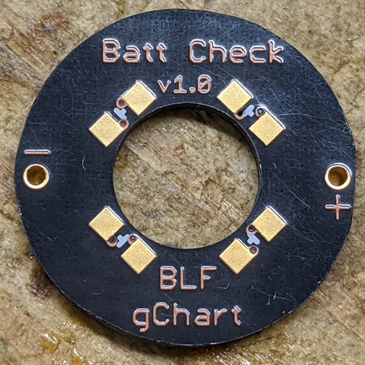
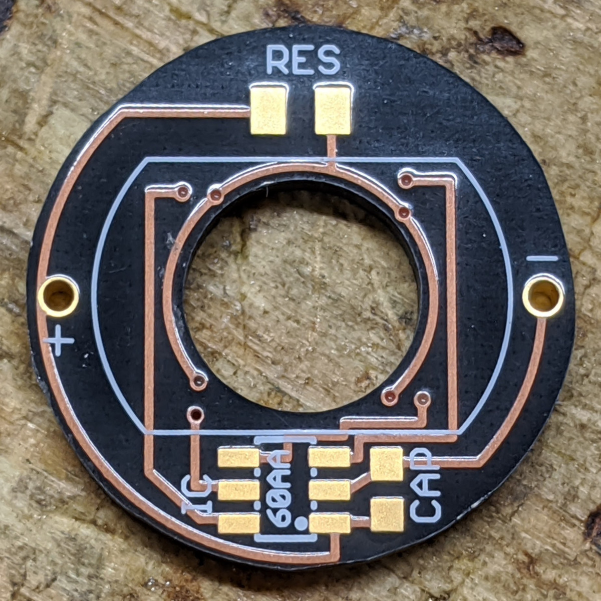
While browsing for some ICs, I ran across these HM1160 chips which are bare-bones lithium battery life indicator ICs. They’re stupid simple and make it possible to create the battery monitoring tailcaps without a fancy teensy-tiny MCU and flashing firmware.
First off, the circuit boards using Oshpark’s new After Dark service. These are 15.8mm: small enough to fit a Tool AA (or SF14, etc) but should also fit Convoy S2/M1/C8/etc.
Here’s it in operation:
Public safety reminder… use protection.
I wanted to see if this chip could get away without a protection diode/FET. NOPE. I don’t want the voltage drop of a diode, so a V1.1 will be coming soon using a small FET for protection.
For the test shown above, I used a 680 Ohm resistor in series to mimic the bleeder resistor (which will have a marginal amount of voltage drop across it). With that in place, LEDs extinguished when falling below these approximate voltage levels:
3.85 V
3.63 V
3.46 V
2.98 V
Those aren’t where I’d necessarily pick them to be, be really it’s not too bad considering how convenient (and cheap!) these little HM1160 buggers are. To be continued…