The first click is the highest level, 150. Second click is the second-highest, 149. And so on.
It may seem like it’s off by one, since level 140 of 150 is 11 clicks… but it’s because otherwise there would be no way to get the highest level. It’s like how the “first century” is from 0 to 99, the second century was 100 to 199, and the twentieth century is from 1900 to 1999.
Does anyone know which tint binning the 4000K SST-20’s Hanks uses have? I’m thinking about ordering a D18 without leds and putting 18 FD2s from BlueSword in it but it would be funny if it appears Hank uses the FD2 bin.
D18 has FB4 and looks like this:
In my opinion, the color is really pretty and I do not see too much sense to fight for FD2. I will just add that the Duv 0.0010 does not change too much, because at 1000 Lm the measurement gave me the same value.
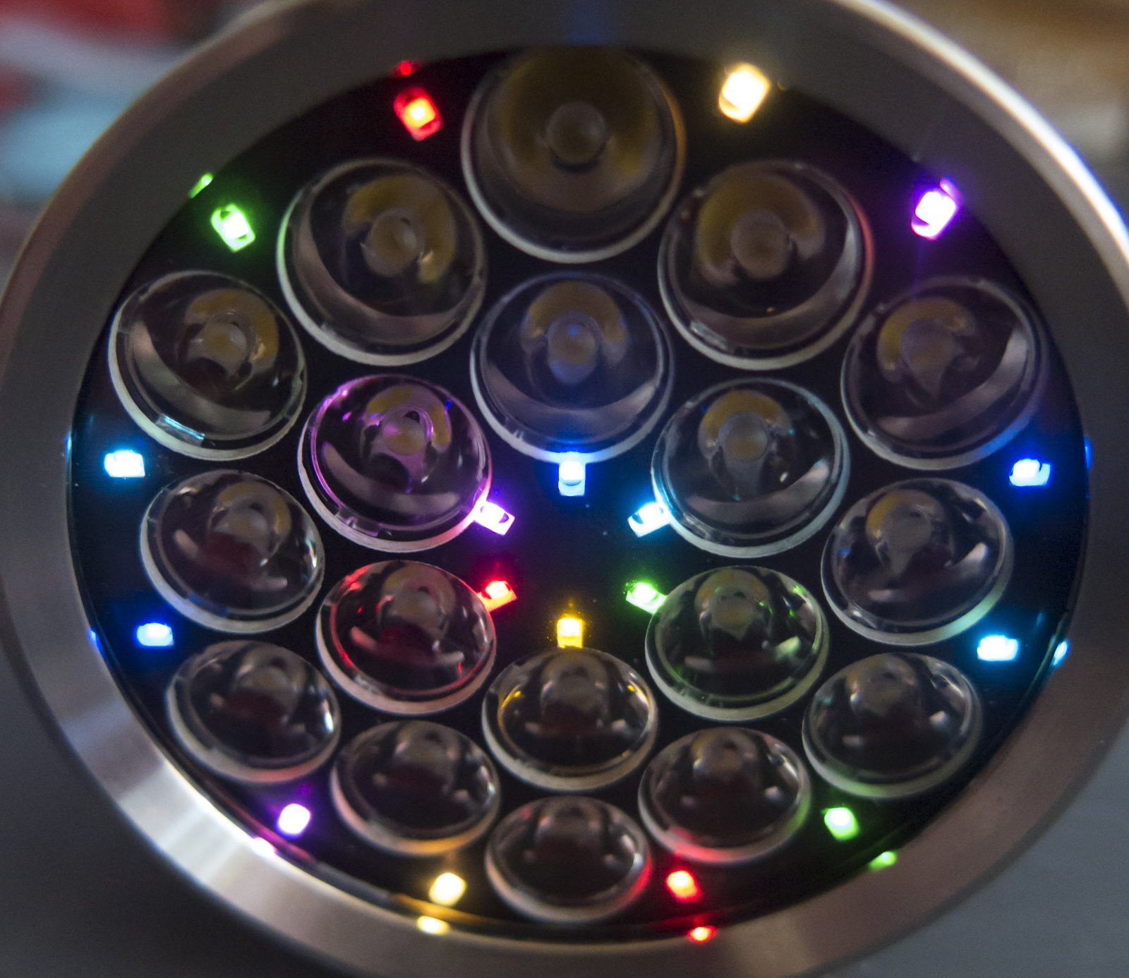
Its seems that there is a little mistake on this protrotype with the AUX LEDs colors order on the external ring. It looks better like on the inner ring when yellow is placed between green and red. Pretty sure you already noticed it but worth mentionning to be sure.
I just took a tint measurement at turbo and got this:
CCT: 4137K
DUV: –0.0024
CRI (Ra): 73.1
R9: –18.5
Rf: 70
Rg: 97
Ra: 73.1
5D is still one of my favorite tint. Looks very perfect neutral white at night time with no hint of yellow when my eyes are adjusted to the 2700K-3000K house lights.
I was tired last night and just wanted to share my results.
The + goes to I+ on the driver, the - goes to G. I tried to bridge R4 but I believe it may be possible to solder the + directly to the furthest pad of R4 (from I+) and have it work.
1. Disassemble the front of head- remove optics, desolder the big red/black wires connected to the mpcb that poke through the middle hole from the driver
2. Remove reverse polarity protection ring by prying and then unscrew the driver.
3. Solder wires to the lighted board/your aux led. Solder those wires through the hole in the mpcb shelf and to the board in the aforementioned positions. Leave a couple inches of wire. (Too much and you’ll have to cram the wires in later, too little and they’ll be too short)
Test everything!
4. Pull the two original thick cables through the mpcb hole. I did this buy soldering a thin wire to the tips of both thick wires to help me pull them through. I can draw a diagram if someone wants it (send me a pm).