Brilliant, and glad to see you with another project.
I wondered how long it would be before lexel jumped in here to bash your work. Very very predictably it wasnt long.
Thank you everyone for your kind comments!
Thank you! Can you not purchase that particular battery in Canada? I'd imagine you will be able to buy it from say Digikey, Mouser or Arrow Electronics. There is room on the GFS16 for the charge pump IC, but I don't think it's very practical due to the high operating current on the order of 10 to ~100ish uA IIRC. Though with a 1mAhr battery, it just might be enough. Regardless, this is a big reason why I chose an e-Switch host for this project. The Emisar D4 is the logical choice.
Yes I noticed the 3V XHP50s at the start of this year, but I didn't really want to go to the expense of ordering my own MCPCBs that fit the D4, for four XHP50s, and I'll have to figure out an optic that fit. Otherwise, yes that would make an even more ridiculous flashlight. I'll be happy to design such a board if people are interested though, some kind of mass order? Though I believe Clemence on the forums here is the guru for high performance MCPCBS. :)
Thank you Agro, yes all will be up. This board is really simple, much less complicated than the switching drivers. The maximum regulated current is dependent on how you set up the current sense, but for now I have it set at 10A with 10bit resolution. I'll take a look at the Luxeon MZ. Good tip on the 20S. I thought the VTC5A was very good already compared to the pink 30Q, but the 20S seems even better! :THUMBS-UP:
Thanks for your feedback and concerns Lexel! For sure there can be improvements to the LED board, but it works and fits the MCPCB just fine, so no need to worry. The resistors can be placed better, but I could have also gone for 0201 resistors, at the cost of higher modding difficulty.
The wires do have significant resistance, though I used AWG18 wire I think, with about 1mR resistance.. As mentioned, I don't use the spring for conduction, only for mechancial retention. Why is why a steel spring is better. Copper foil is used for bypassing. Regardless, as mentioned, I think a CC FET driver doesn't make sense from an engineering point of view in terms of reliability, consistency, or safety. Practically speaking, with the right safety features and physical construction, it can make a good flashlight with a fun 'turbo' feature. The main functionality of this driver is a no-nonsense CC linear drive. The DD FET is more just for fun. :) Since we're going for ridiculous here, thought I could go a little further. Having a lower R_ds_on for the FET also reduces junction heating, which keeps R_ds_on low as current flows.
The main practical features of this driver is not the DD FET though. I really like the other features, and I think having a CC regulated driver for the Emisar D4 is not a bad option. Music reaction, is a fun gimmick too.
I'm sure Lexel just wanted to show some concerns with his experience building drivers. :)
Thanks everyone for the feedback!
loneoceans it is very good to see you agian!!
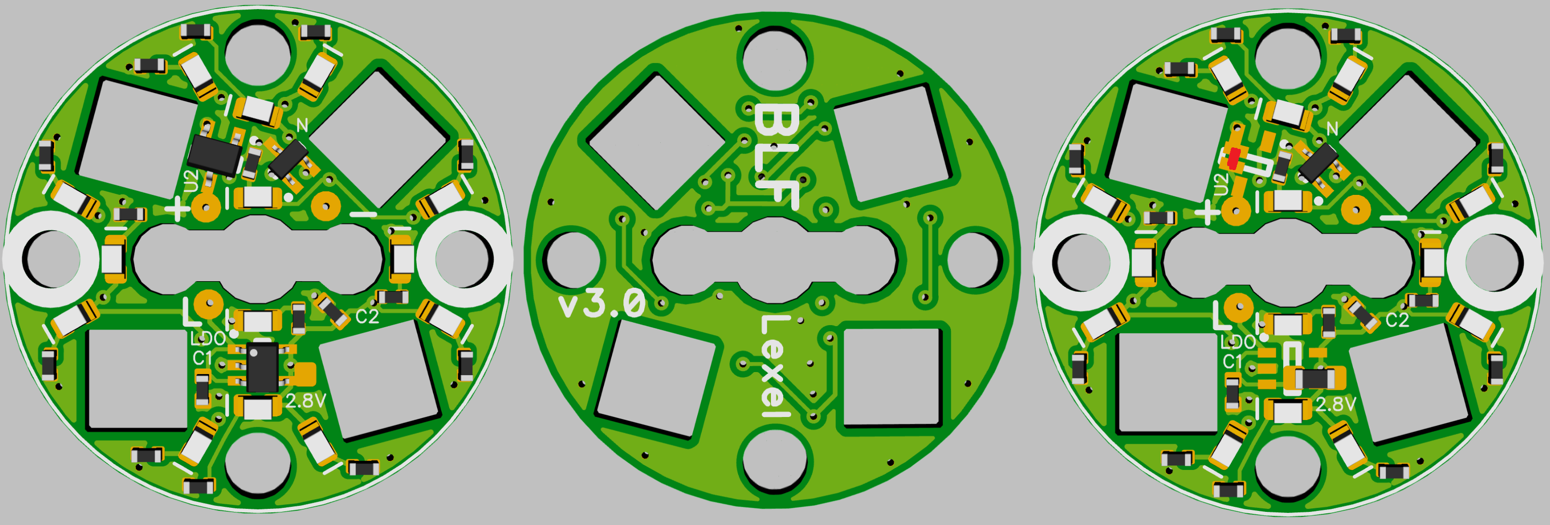
Wow this is the first time I see so many unusual and new feature on this driver ever! This is a lot of unique ideas. loneoceans I have good success with your gxb172 driver and now this makes me want to buy Emisar D4! A question is, do you know if this will fit new Emisar d4 version 2?
I imagine, with Luxeon Vs in your D4 as in mine, that there's not much issue maintaining regulation even at 10A. Heat should be your first problem, and voltage sag eventually your second, not emitter Vf :P
I could not find a source for the battery in Canada, the new battery postal rules make shipping into Canada too difficult it seems. The super capacitor I’m using works really good for the first ten minutes and after thirty minutes the output has really dropped off. Its fine most of the time and I don’t have to worry about over discharging the battery.
I see a lot of uses for this new driver you made, especially if it can handle higher voltages. Would two amps at 4S and 0.5 amp at 5S be possible?
The microphone might be the best part. I don’t know how well Atmega’s can recognize words but if it can identify the word “Beetlejuice” (its a silly movie from long ago) and go into a crazy strobe mode if it hears that word three times I’ll probably have to build four.
You’re probably spot on…apologies for jumping on you Lexel.
Unfortunately the Atmega328 isn't powerful enough to run a voice recognition engine... but would not be hard to make it responds to claps or loud single sounds (again I'm not sure if I recommend this because you certainly don't want to turn this one when it's in your bag for example).
However, you are tempting me to throw in an ARM Cortex M4 on the flashlight and run a voice recognition engine on board... there's certainly enough space ;)
Program the modes with morse code
I myself did the first D4 Aux board with not cut through holes
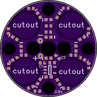
It just was not so easy to solder the LED wires, even with 0.6mm thin boards, having resistors there that may short out with bad solder skills or equipment isn’t helping
I placed even LVP chip and low side N-FET on it with 0402 resistors with no issues, just route a ring on top side with resistors and back side with LED-
looking on a flashlight with Infineon FET that part is not a weak link, probably even the MCPCB is worse
so many resistances adding up
- springs (even bypassed),
- wires,
- MCPCB,
- copper on driver,
- FET,
- tail board,
- tube
- soldering
This is more and more interesting! just not too long ago having 1000 lumen in a flashlight is next level. today we have possibility of 100w boost driver and now this one with audio reaction.
loneoceans I will plan to build one of this when your design is ready! I hope it will fit new emisar flashlight! (d4 vers 2)
I guess not long before Lexel copy this driver and offer one with similar design! Let see if lexel will suddenly have charge pump on his fet driver and make a fet and cc driver…
I’m not sure a tiny microphone hidden inside a light would be sensitive enough to work. I don’t know much about ARM’s either, were some of the M4’s IOT capable? Maybe a cell phone could recognize the words and command the driver.
I know its totally off topic but I am curious about your Tesla coils. Do you touch the high voltage, use it to light up fluorescent lamps you are holding or just stay back and watch the light show?
Nicely done, LO. I love to see outside-the-box ideas.
What chip did you use for controlling the FET in CC mode? I assume the FET will be burning off the excess voltage and that a good thermal path for it is essential.
Just throwing this out there… Are there any FETs with an electrically neutral thermal pad? I’ve never seen one, but I haven’t looked that hard.
Skip that step and put the FET on MCPCB like L4P.
Great idea. It could be like programming BOSS flashlighs but with the sound instead of light!
Wouldn’t sound pretty. Unless the stream would be steganographically embedded in music. Then programming would take looong. But would be pleasant. ![]()
You had me at:
That’s the ONLY thing missing in the D4 IMO.
Fuggin’ ’ell, YAY :heart_eyes: ![]()
Thanks everyone again for your kind words.
I don't claim to have the skills to be able to implement a neural network on a micro, but fortunately, lots of other people are. Here's an example: https://github.com/ARM-software/ML-KWS-for-MCU. Should be able to get this to run on a Cortex M4 core. But let's not get ahead of ourselves; maybe a future project, but definitely not for this one right now! 
Unfortunately it would be hard to add phone connection to the driver (e.g. via bluetooth), mostly because of how the driver is completely surrounded by metal, and a bit too much time needed to write the firmware for both the driver and the phone~
Anyway I hope this driver will be useful in the end since the main useful features are the constant current drive mode, good temperature regulation, good firefly mode, aux led control, and a little bit of fun with the microphone. The DD FET mode is impractical in my opinion, just a for-fun thing, and optional to even install that half of the driver.
The maximum sustained thermal load the D4 can sink will lead to only a few hundred lumens output.
@gchart, this means thermal sinking of the CC FET is not as crucial as one may think. That said, I found a perfect silicone pad to interface between the fet body and the metal D4 shelf, so thermal sinking is decent.
@i42dk, glad this feature is something you like.
@WTF, yes my main hobby is in big power electronics. For my coils, I'm just standing back to enjoy the show, and to keep safe. They do light up fluorescent bulbs and other low-pressure tubes from a distance though!
Have a great day everyone!
Very interesting and inovative linear driver. But I have one question whats mean no-nonsense linear drive. You just no use a sense resistor for current measurements? What method do you use for current measurements. Maybe you just measure the Rdson of the MOSFET via voltage drop. Also do you use dedicated Charge pump IC for mosfet driver, I assume you also use some sort of transistors driver to turn on power MOSFET. Most of charge pump IC only have 2X of input voltage so it is interesting how do you boost voltage to 10V from single battery.
ha i think loneoceans mean ‘no nonsense’ meaning it is a linear constant current driver that just works without trouble. I think i see sense resistor in the photograph which is R1.
also my guess is loneoceans using some charge pump gate drive ic like this one: https://www.analog.com/media/en/technical-documentation/data-sheets/19812fs.pdf. for example it has charge pump with “internal voltage tripler allows gates to be driven without the use of any external components.” This explain 10v from one cell, but maybe not this ic since it has 7.5V max, but still good enough!