Used this “technique” on certain custom chargers based on generic CC/CV supplies in the past. It ended up working very well.
Recently made some more voltage drop measurements on a few schottky diodes applying a low constant current across them. For example, measured ≈270mV of drop on an SK54 (1N5824 equivalent) when ≈90mA of current goes through it. A 20SQ045 is at ≈250mV with ≈100mA if I do recall right.
As you may guess, setting a diode in series with the charger's output will effectively lower the termination voltage by the diode's Vf at the charger's termination current.
This can be of service for modified gadgets with very or ultra long service life batteries in mind. And for those of you who may want to add a selectable output voltage switch to a existing chargers using SPDT switches and a few schottkies. A couple schottkies or a standard rectifier should drop the standard 4.2Vmax to LiFePO4 levels.
As an unintended bonus it will also protect TP4056 chips from reverse polarity mishaps where removable batteries are involved.
I really like my hobby charger’s ability allowing me to select a charge voltage of 4.1v rather than 4.2v, Doubles the life of the battery by only charging to a capacity of 92%. Voltage / capacity
Now that I'm back here, I'll pinpoint the main article which inspired my li-ion loving care practices: BU-808: How to Prolong Lithium-based Batteries @ Battery University. Suffice to say I had already experienced unexpected low cycle life with some batteries (mainly in smartphones).
Batteries have evolved. Many modern quality batteries/cells display higher cycle life and higher energy density at lower charge voltages than the figures claimed in the above article. Looking at the discharge curves of many of the reviewed cells at lygte-info.dk I can clearly see most cells displaying ≈70% or more available capacity when charged to 3.92/4.2V (14/15 of maximum charge voltage). So, at least 65% of the maximum rated energy is available at that point in most cases.
If you subtract 250mV from a 4.2V charge, you should get 3.95V instead. I don’t see in this thread a way to get just a 100mV drop from termination voltage, except where roguesoul said his hobby charger is capable of doing it by selection.
Whereas a Si diode drops 0.7V at Vγ, a Ge diode would drop only 0.3V.
In my always-on car voltmeter, I had a big 0-1mA meter (labelled 10V-15V), so had to drop pretty much 10V exactly for an accurate read. Used a 9.1V zener diode and pair of plain ol’ 1N400x diodes to drop that ~1V, about 0.5V each at low currents. If I would’ve cherrypicked zeners, I could’ve gotten it spot-on, but didn’t care about 0.1V here’n’there.
So even if a Ge diode drops 0.2V, it’s at least closer, maybe even closer than with a Schottky diode.
A saturated transistor could drop VCE to 0.1V or less, too.
Unno, seems smarter to have the thing just built-in, for 4.2V cells, 4.3V cells, “storage mode”, and “long-life mode”.
This is a sort of generic trick. If you really need fully custom output voltage a CC/CV power supply/module is due, if you can live without termination that is. This is no problem for me.
Using a charger with 4.35V output and a schottky should deliver something around 4.1V. The exact figure depends on a combination of termination current, diode size and type plus its operating temperature (!). Just re-measured a 20SQ045, 264mV at ≈92mA, the room was a bit cooler than the other day with the SK54. With enough diodes in parallel to share a really small current each diode we could get into ≈200mV territory, but that would look pretty (>ლ) frankenstein.
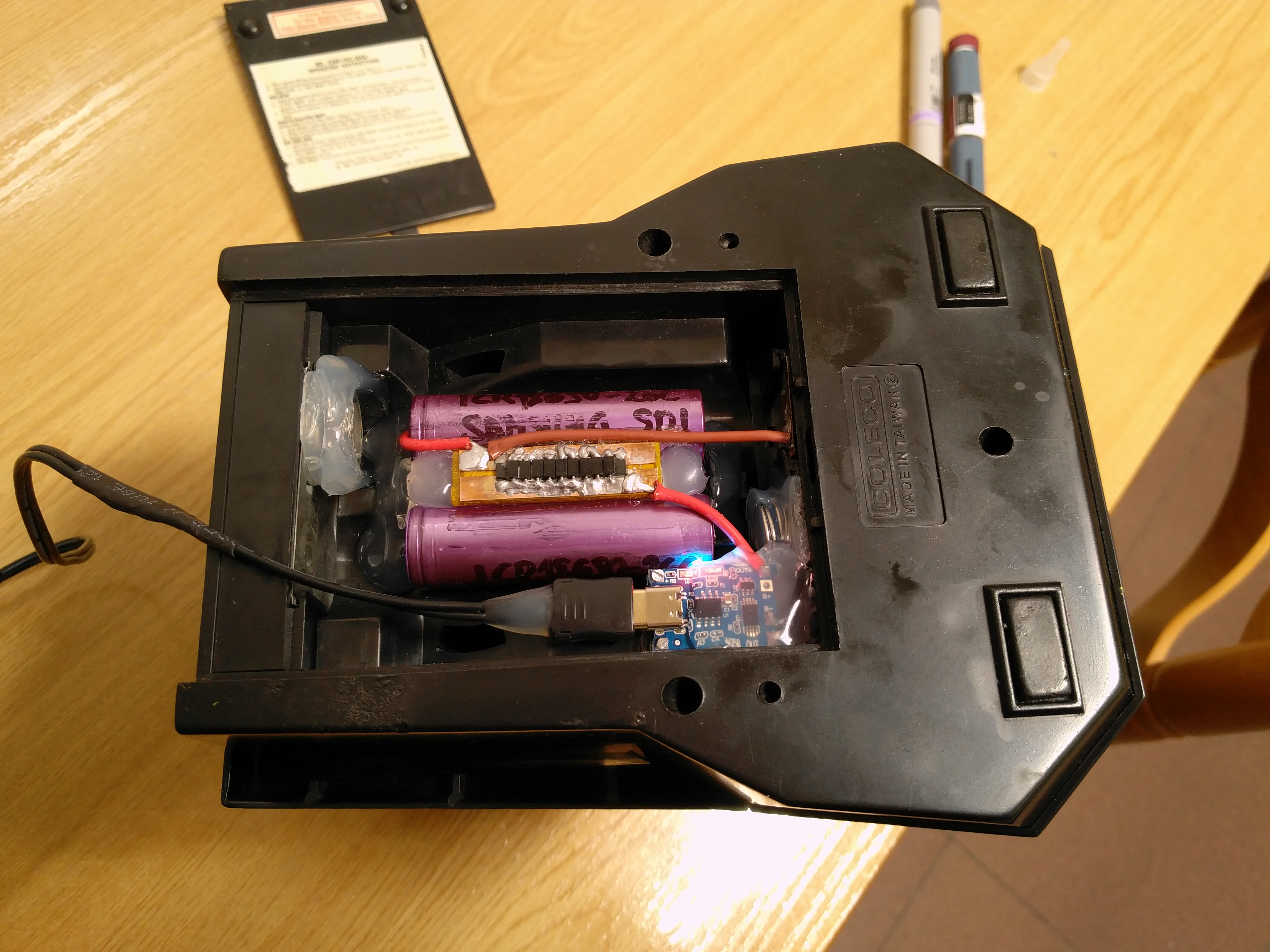
Well, just finished this pilot experience. Two stacked TP4056 boards with protection circuits being used. The boards charge 2x salvaged Samsung ICR18650-26C cells still clocking 2150+mAh each, with a nice bunch of schottky diodes in series: 8x SS54s + 2x salvaged SK34s plus 1x SS54 in reverse for protection circuits to work. Left the stuff charging a few hours and came to measure the final cell voltage after unplugging with both boards showing their blue (2nd) led lit: 4.005V.
I am bit surprised it went that high, I think the board with the highest Vout was ≈4.16V.
Thank you, Barkuti. This might be a project for next year. Last spring I read your methodology of not charging to 4.2v and have been removing the batteries between 3.90 and 4.00v, even for the first charge. Do you think that is better than an initial charge of 4.2v since the manufacturers say “fully” charge before using? Just curious as to whether it matters. Thanks again.
Helios azimuth initially charging to 4.2V is no better than just going up to something lower, except for the fact that you load the cell with more energy. Notice that, in this case of ours, charging up to ≈3.95V would be considered a full charge. Going up higher won't render any cell health benefits, quite the opposite. ;-)