well, it does seem like it’s inversely proportional to that resistor. i found this pdf about the driver ic which is used. and it indicates same thing i guess same should apply for my driver too ? does this apply for all buck drivers ?
Wow that MP3431 datasheet shows 97% efficiency @1A which is around the current I need. Just need a driver with more evenly-spaced or configurable modes, and a ~3V cutoff voltage.
EDIT: Appears to be PWM not constant current :person_facepalming:
NarsilM - Neolithic Advanced Research Superior Intelligent Light Module
Yea, right....
From the source code: "the sword wielded by Isildur that cut the One Ring from Sauron's hand"
Let me see, I started working as a programmer in 1979, also bought the very first IBM PC for my own home use about in '82 or so. Also in 1981, started doing my first consulting gig at $17/hour - hit the big time!
I should add that over these 40 years or so, I've done a ton of firmware projects, most or all where the firmware had no name, least that I can recall, because basically, hardware such as fault tolerant server, graphics controller, terminal, typesetting system, treadmill, or any other device I've written firmware for gets only one functional version of firmware and is an inherent part of the product. So for example I might have built in a feature in the treadmill firmware to pause/resume, but that's a feature of the mill and listed as so.
In this BLF/flashlight kind of environment though, a name or way of identifying it is more important since there are many choices. We could have gone by the author but that has it's problems and is not conducive to the open source, open nature of the forum here. Also could have used some acronym that stands for something clever, but no one will really remember or care anyway, so Narsil or NarsilM is about as good as anything. I followed TK's lead here for using names like this, and Anduril, of course, is the natural successor to Narsil. In fact as I recall, TK asked me privately if it was ok to use that name, and assured her it's no problem at all.
Yes JasonWW, Loneocean’s driver is a tease but I don’t have that kind of time. I’ll just stick with the H1-A mod until MTN has their BST series back in stock.
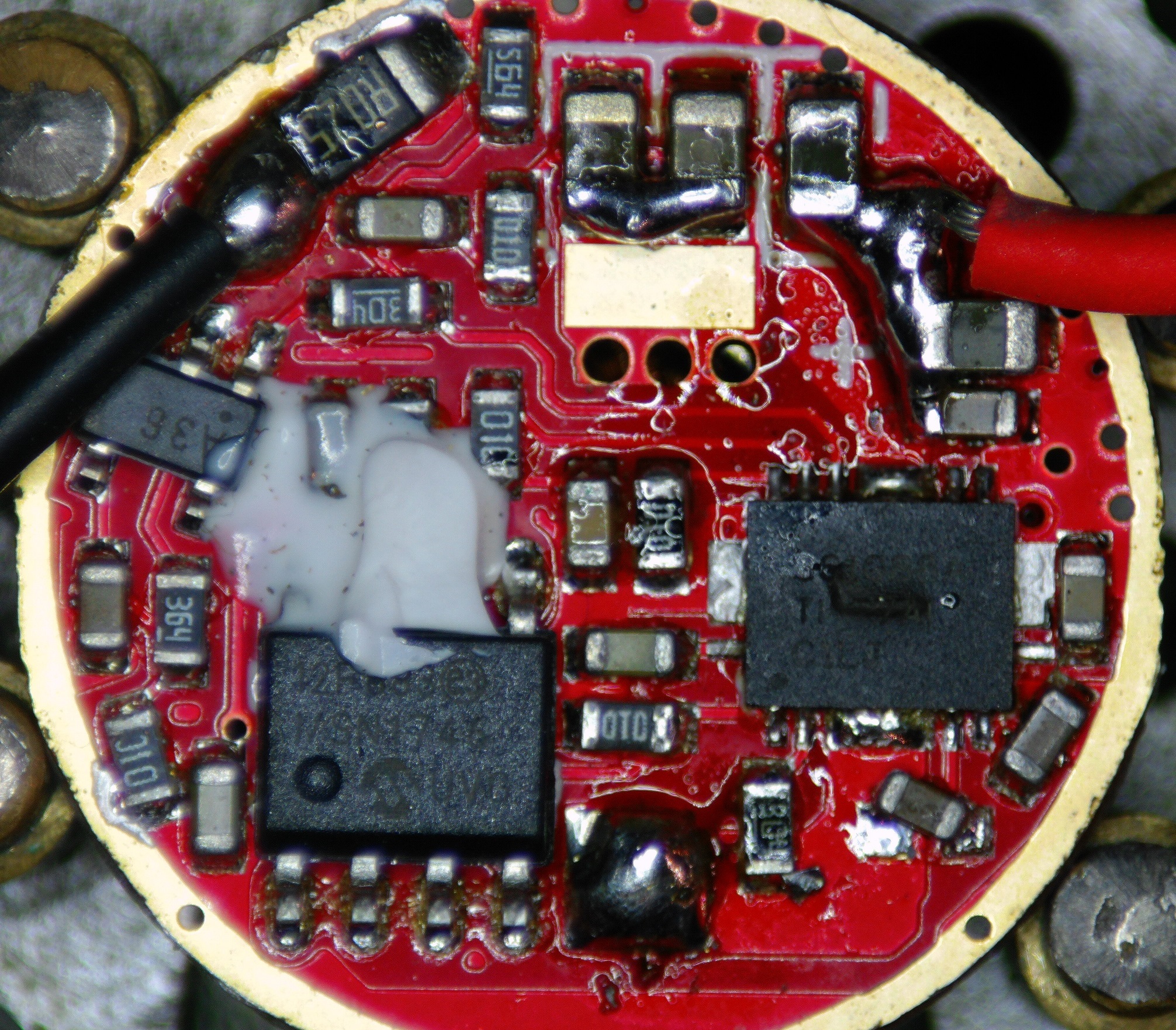
I accidentally broke my old one marked 2R2 and now I’m getting a 3% efficiency drop (92% to 89%) @1.25A with the new one marked 1R5. Well that kinda sucks.
I still have the old driver with 2R2 inductor, but I absolutely won’t do anything that might damage the newly modified driver, because changing the resistor is a PITA. Let me know if there’s a sure way to replace the inductor. While at it, may as well go bigger than the 2R2.
Unsolder the current, solder the new/replacement one. This is easy. If you have some parts lying around, that is. I do, but guess I may be too far away. O:)
The solder joint near the resistors is risky for me. I’m going to skip this mod, use this H1-A as is for now, and then get a MTN BST driver when they’re in stock.
i’m having strange issue with a buck driver, currently it’s having 3x 0.24 ohm current sense resistors which means output should be 2.5Amps right ? but it outputs more than 2.5A when i try to run 3x osrsm white flat + 1x Xml leds in series.
i’m powering the driver via motorcycle charging system ( driver is designed for it since it’s from motorcycle auxiliary light) , input and output current hovers around 1.3/1.5 amps when motorcycle is idle @ 13.2-13.8v, but as soon as i increase RPM, voltage goes upto 14.2v , and led driver outputs more than 2.5Amps and goes upto 3.2Amps to leds. i get that when input voltage is not sufficient the driver won’t output enough current to the leds, but when the input voltage is enough , it shouldn’t deliver more current than it’s supposed to, right ?
now here comes the strange part, when i remove 1 xml led from above arrangement and run only 3 white flat leds in series, everything behaves normally, output current never goes above 2.51Amps.
any idea why running 4 leds in series instead of 3 , increases driver output current ? btw driver is designed to be used in 9-36v range.
thanks .
A little update, i tried running 4 leds in 2s2p arrangement, and driver output doesn’t go above 2.52Amps. so it works normally. but efficiency goes down. compared to 3 leds in series.
1. when driver is running 3x leds in series - input voltage*input current = 14.2v*2amp. =28.4w. ( output is 24w, so 84% efficiency )
2. when driver is running 4leds in 2s2p - input voltage*input current = 14.2v*2amp. =28.4w. ( output is 16w, so 56% efficiency )
i really want to run 4 leds, but not if efficiency is really that bad. with 4 leds i can use 4x 20mm tir optics, which will give more throw compared to 3 optics.
slopegatri70, such driver does not seem to be able to handle 4 emitters in series with so low input voltage. For example, 4 white flat emitters in series require ≈12.5V at 2.5A, plus any cable and connections overhead. The effective input voltage into the driver is just very little above that, if at all, and so it cannot work properly.
If you are adamant in driving 4S emitters with such driver, raising the input voltage may work. For that, get some DC/DC boost converter you can fed with the driver's input and then attach the boost converter's output into the driver's input. Suffice to say, adjust the boost converter's output voltage to a sufficiently high value, 14+V.
Actually the input voltage i checked was on driver itself ( 14.2v), charging system gives 14.4v so almost 0.2v drop. i can’t use any dc/dc boost converter because it will stll lower the efficiency. ( motorcycle generates 11.5amps of current, only 4-4.5 amps is left for auxiliary lights after i subtract power requirements of headlight/turn signals/pump/etc.
i really thought 14.2-12.5=1.7v would be enough for this driver. i guess it’s not enough. maybe i should use 3 leds in series with 2x 20mm + 1x 26mm optics. it will have same or maybe a little bit more throw than 4s leds.
or maybe i should change the driver, but i don’t know if there’s any high quality efficient drivers available with low voltage drop.
man this experiment( modding the lights to reduce glare) is costing me alot, and there’s very little progress so far. (
I got also just from one German Guy 2 dead of those with 2R2
both with burned all in one switching chip
and it seems no one checks driver for not properly soldered parts, it is possible to let that do in a good PCB fab automatically