Yes, this is a technical necessity. This driver circuit cannot work stably with lower currents, which are needed for a real moonlight.
Therefore, the minimum is 3 lm.
But instead we have controls without PWM at any brightness, 3-850 lms ![]()
Are you sure about that? When I removed the clip some paint from it rubbed off onto the anodizing, but it cleared up just as easily.
Yeah, unfortunately, that’s an issue with any single-channel FET-based light, regardless of whether it uses PWM or constant current. And more generally with almost any type of power circuit, there is only limited resolution to work with.
In this case, let’s say the highest mode is 850 lm and there are 8 bits (255 steps) worth of resolution. That means each step is 3.33 lumens… which is probably why the bottom mode is rated at 3 lm.
To work around this, people sometimes use 10 bits of resolution instead, for 1023 steps. And in that case, the step size could be as small as 0.83 lumens. But with most circuits, the bottom end tends to be fairly unstable so we can’t count on the bottom few levels being as reliable as the rest.
Pushing the resolution up farther gets difficult too, because it slows down the cycles. When using PWM, the pulses end up too far apart so it looks like a strobe light. Or when using constant current, slower cycles require bigger inductors to smooth out the signal so the entire light gets bigger and more expensive.
A more effective method is to use multiple power channels instead. So, for example, take the BLF-A6. There is one channel which goes from ~6 lm to 1600 lm in 6 lm steps… and one which goes from ~0.2 lm to 130 lm in 0.5 lm steps. The end result is that it goes both lower and higher and provides significantly higher resolution where it matters.
I’d like to see the bottom channel go even lower though, like 0.1 to 30 lm in 0.12-lm steps. Then perhaps a middle channel which goes up to 300 lm in 1.2-lm steps. And on top, a third channel which goes up to 3000 lm in 12-lm steps. This just requires more pins on the controller, more components on the driver, and slightly larger firmware.
I suspect I’ll be fine with the 3 lumen low, as much as I love my sub-lumen moonlights. I just won’t use it for “don’t wake up the wife” duty.
Thanks for the insights on low-level moonlights, TK. I understood it before as basically “can only PWM 8x7135 so low, so split one off into its own channel and PWM it alone”, but it’s interesting to see the issues presented by other driver types.
One more measurement to add - with the locator LED on beneath the switch, the standby drain is 67 μA.
In this case, physical resolution of ADC is +–512LSB (10 bits, signed) and effective resolution is even higher (~24 bits). Analog stabilizer has to sustain 3 lm in spite of changes in outside conditions. 24 bits math with integration of rounding error (accounting of remainder of division) is used, which is bare minimum.
That problem is easily averted with the use of uncompromising application of Delta-sigma modulation (DSM).
For example, utilized here PWM has 137 steps (just a little bit more than 7 bits) and frequency 29.2 kHz, however effective resolution is 137*2^16=8978432 steps, which is a little bit more than 23 bits. I can set PWM frequency and required resolution independently. But modulator imposes restrictions on frequency of interrupt calls:
//Modulator (PWM Extension)
    //R0 - ZERO
    //R3:R2:R1 - PWM
    //R5:R4 - PWM_DSM
    //R6 - PWM_BUF
    //R7 - SREG1
over1:  in  R7, SREG    //Timer1 Overflow Interrupt
    mov R6, R3
    add R4, R1
    adc R5, R2
    adc R6, R0
    out OCR1B,  R6  //PB4
    out SREG,   R7
    reti
//-------------------------
    //PWM Init
main:   ldi R25,    LOW 32768   //PWM = 42.5LSB
    ldi R26,    HIGH 32768
    ldi R27,    42
    cli
    mov R1, R25 //PWM = (42<<16)+32768;
    movw    R2, R26
    sei
    rjmp    PC      //while(1);
This code requires 16 clock cycles, so one can’t reduce PWM resolution lower than 5 bits (32LSB). It is speed limiting code block, so optimisation is of high priority. In impulse drivers I use 5 bits 250kHz PWM + 16-24 bits DSM = 21-29 bits 250kHz with clock frequency 8MHz (without PLL, it causes only harm).
C- code looks like that:
uint32_t pwm=0;  //PWM Value (global)
//Modulator (PWM Extension)
void TIMER1_OVF_vect(void){
    static uint32_t pwmdsm=0;
    pwmdsm += pwm & 65535;
    OCR1B = (pwm + (pwmdsm & 65536))>>16; //PB4
    pwmdsm &= 65535;
}
//-------------------------
//PWM Init
void main(void){
    cli();
    pwm = (42<<16)+32768; //42.5LSB
    sei();
    while(1);
}
However, it is much slower. Assembly code just overflows the variable of the fractional part of the PWM and the carry flag adds to the integer part of the PWM. The larger the fractional part, the faster the whole bit of rounding error adds up, and the more often this integer value is added to the LSB PWM. For example, if we have a 42.5 value in PWM, then it is 42 in the high byte and 32768 in the two lower bytes. These 32768 will overflow uint16_t once every two PWM periods, and the PWM duty cycle will jump between 42 and 42+1 with a ratio of 50:50. This is the simplest implementation of a 1st order modulator, but it is quite fast and efficient here.
Such modulation has a number of useful properties. It gives a blue distribution to the quantization noise spectrum (blue noise). So quantization noise is displaced into the HF region — the lower the frequency, the lower the noise amplitude. Capacitors and our eyesight can do reduction this modulation very well. For example, for indication I use pure DSM (1 bit), just manually switching MCU pins. In Meteor, this is modulation at a frequency of only 5kHz per channel and a resolution of 16 bit, which does not prevent the backlight from working quite comfortably in a wide brightness range. Unicorn has a slightly higher frequency.
That way, we have 23 bit PWM and 24bit PI regulator. The regulator smooths the noise of the ADC in a natural way, averaging its readings and allowing you to adjust the LSB fraction. However, in the linear regulator there is a problem - it makes little noise. Oversampling does not work well. I had to artificially increase the current ripple by lowering the PWM frequency on the MOSFET gate, and it still was little help. At some point, oversampling simply ceases to work and the regulator falls to full zero. Therefore, minimum is 10mA (1.5LSB). At the same time, the remaining error in ADC, along with the 20x amplifier, something around +–0.2LSB is the usual result.
Yes, low currents can be obtained right from MCU pin through a resistor. From <20mA and up to sub-microampere values. Using DSM.
As you can see, resolution is not a problem here. The real problem is the lack of noise from the operation of the regulator at low currents. By the way, 137 was not chosen by chance - this is a prime number that gives the minimum correlation of noise from PWM with the ADC sampling frequency (clk / 256).
And ~110 μA with the Red + Green indicator LEDs :)…
P.S. That is the runtime chart for vertically standing flashlight in closed room:

At 130 min I entered room and made a draft. That’s how thermal control works in Unicorn. If someone has rugged lines - you do something wrong.
It’s an interesting idea for sure. It basically does a dynamic trade-off between effective resolution and PWM speed. At low resolution it’s fast, while at high resolution it’s slow. But I don’t buy that it can actually do 23.098 bits worth of effective resolution, because on a 8 MHz controller that would give a cycle speed longer than one second. At that point, it’s not helping with resolution… it’s just making the signal less stable.
But at less extreme resolutions, the speed would still be fast enough to be useful. For example, 16 bits could run at 122 Hz, which would not be very noticeable when it is only a ripple instead of a full on/off pulse.
Digital resolution may not be an issue with that method, but it’s still limited by analog resolution. Getting a single drop of water from a fire hose is difficult regardless of the method used. Much easier to get a single drop from a syringe.
If I understand correctly, a low-resolution sensor may have been used. It can be difficult to find phones with good light sensors. I am lucky to have one with 13.3 bits of resolution (10,000 levels), but with newer phones it is common to have only a few bits worth.
In any case, it is impressive what you have achieved with the Unicorn. Welcome to BLF! ![]()
Great first post Inferion and welcome to BLF. Looking forward to the discussions to come.
Yes, the steps in the graph are just low measurement resolution - that’s why I only mark every 10% on the grid. I’ve been meaning to hunt down a finer sensor, but I really want to get away from using a phone to record and haven’t found a good luxmeter that will either record or output to a PC at a good price. It’s on the to do list, but certainly those little steps aren’t caused by the light ![]()
That graph looks very smooth.
How/why is the thermal regulation so much better than the typical budget flashlight we are accustomed to ?
Is is because of lower max output (so smaller range of scenarios to cope with) ?
Or improved driver/components ?
Or better algorithms ?
Very interested in replacing the LED on the XP-L HI V2 3C. Please tell in more detail about the replacement procedure
it’s like in any other unglued flashlight, nothing special, just unscrew the bezel, remove TIR lens, unsolder the two wires from the MCPCB, replace led from the MCPCB outside the flashlight and mount all again
Thank you. What will be the changes after replacing the XP-L HI V2 3C? I have no other diodes
Way more throw (240m against 125m stock) and better tint (for my taste, I don’t like the green/yellow tint from the 4000k LH351D )
I really like the light with the XPL Hi Led
Probably a combination of things.
A lower power-to-mass ratio makes Unicorn’s regulation easier than something like an Emisar D4. And making specific code for just one light is an easier problem than making generic code to regulate a wide variety of lights. However, it’s also very likely that Inferion made a more accurate algorithm, since they approach things more formally like a mathematician instead of just trying things to see what works. And I’m guessing the higher-resolution power controls help too, since it can make very small adjustments. And based on the graph, it also looks like it aims for a very narrow optimal temperature instead of aiming for a wider temperature window.
So as far as I can tell, the differences are because of two things: It was a somewhat easier problem, and it was solved better. It’s not easy, but Inferion did a really good job with it.
Thermal regulation can be sub-optimal in a lot of different ways. For example, if the adjustments are too large or too slow, it can overshoot and oscillate. This happened on ZebraLight’s generation 4 lights, though at least the amplitude of oscillation was reasonably small:

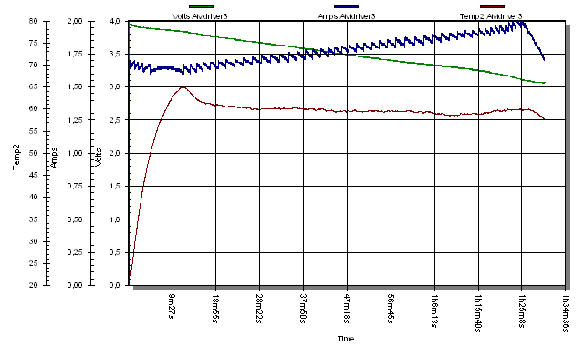
Another common pattern is a zig-zag, especially with FET-based lights. The output sags over time as the battery voltage drops, and then the controller steps up to compensate. The individual step size depends on the PWM resolution, and the total amount adjusted at each step-up depends on how wide or narrow the temperature window is. Here’s how that usually looks: (at the end, the sag is pretty fast, and eventually it can’t step up any more so it’s running in direct drive)

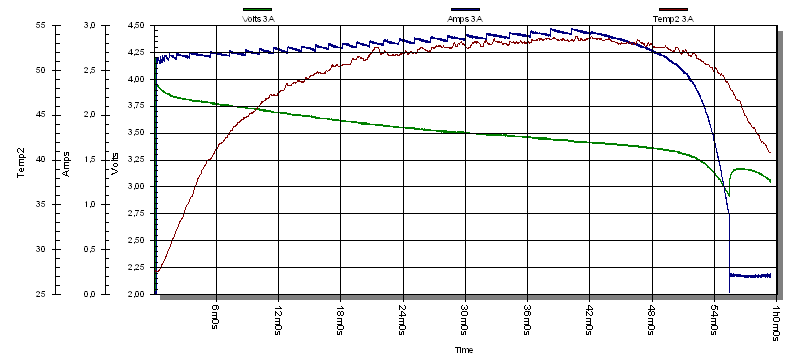
A similar pattern can be seen in other FET-based lights like the MF01S. The result is actually pretty close to optimal, but it could probably stand to have a narrower temperature window to make the step-ups smaller and closer together: (there’s also some visible noise at the end caused by the driver hardware, but the firmware can’t do anything about that)

With something smaller which stays at current-regulated levels, the result looks more like the Unicorn. Output slowly climbs as voltage drops, because there is less extra voltage to burn off. However, it looks like it overshot the ideal level a bit at the beginning before correcting itself:

Or with recent FW3A lights, the regulation generally stabilizes pretty well but it can sometimes wobble a bit on its way to that steady state:

On a light with a lower power-to-mass ratio, the results are usually pretty decent. This graph isn’t as smooth as I’d like, but it’s not really bad either:

Of course, when things aren’t tuned right, the results can turn out pretty bad… like with large oscillations or continuous searching. It really depends.
It is utilized in the most precise and noise-free (but somewhat slow, yes) ADC and DAC everywhere. For example, your smartphone has MEMS microphones with PDM output (example), that have 1 bit, frequency 3.072MHz and dynamic range 105dB. SACD format also has 1 bit and frequency 2.8224MHz. Audio Delta-Sigma ADCs and DACs run at 12.288MHz (though they are usually 3-bit) and have dynamic range up to 130dB. These modulation frequencies are enough for our hearing at much higher frequencies, and moreover we have 8MHz and we work with more inertial eyesight…
By the way, digital audio requires dithering, that is essentially the same thing that we discuss here. And there are great video about that:
It applies even for pictures and present in our monitors, which are, in fact, 18-bit, rather then 24-bit.
Yes, 4MHz/137/65536=0.446Hz, but is should be noted, that discussed restriction of arithmetics is much lower than natural noise of analog part at the same frequency. Concept of quantization error disappears and only white noise of the analog part with a normal distribution remains, which is perfectly fit for filtering. 23 bits are used here just because ~16 are not enough, and ~32 are excessive. At the same time with ~24bit we still have to use dithering. This means that the LSB is noticeable amid analog noise even here.
That is not correct. Instability is introduced by nonlinear distortions because of low resolution of DAC. For example, lets take PWM with 10mA step and offset 7mA (for specific current conditions, such as supply voltage, temperature, etc.), and a setpoint of 35 mA. What should the regulator do? He will periodically jump sharply between 37 and 27mA, achieving an average value of 35mA. He will struggle with non-linearity – one moment the regulation error is +2mA, then all of a sudden it is 8mA, and there is no way to get to zero … This is the way the integrator works in any control system, and it is the basis of the DSM we are discussing. Here it is implicit, but it is here, and operates at a very low frequency. If you try to reduce it as a “noise”, catching on the nearest integer value using hysteresis (which is often done by mistake) these 37 or 27mA will float from external factors, and from time to time jump to the next step sharply and quite noticeably. Here is a good example of such driver:
It is easy to notice with our eyesight, especially for a number of smooth effects, like ramping. In this case if noise level exceeds the software hysteresis it will be much worse. There will be strong jitter. And it does happen from time to time in practice…
If modulator is used, this effect of jumping between these steps has high frequency and is averaged by natural filters (including the integrator itself in the control system), and the control system, like our eye, sees the desired 35mA, which are stable. Here is an example of such implementation:

Yes, somewhere there at 0.5Hz it will jump to 1/65536 from the basic resolution of the PWM (Vcc/137), but how much is it noticeable to the eye? Are jumps 65536 times larger easier to spot? And it is also important to understand that in this circuit a 1/137 Vcc change in the gate voltage leads to a change in current by a factor of S. We have S = ~70 (SiA448DJ). I.e. jumping on 4.2V/137=30mV we jump on 30mV*70 = 2.1A! In my example, the regulator works with units of milliamps, how so? ![]()
It won’t be noticeable at all, because energy at 122Hz proportionally lower relative to the 250kHz (2048 times lower), and the output of RC-filter has the same ripple level. And it works across the entire spectrum simultaneously, up to our conventional 0.5Hz at 24 bits. Eyesight also acts as RC filter, and the non-periodicity of the process makes the detection of modulation in motion a more difficult task compared to PWM. Even cameras do not see it, unlike PWM, which, at the same time, has a lower resolution.
There are a lot of advantages, and for many years I have been surprised that very few people approach the issue of signal processing from, actually, the theory of signal processing … They intentionally discard the least significant bits of ADC, because they are «noisy», use bare PWM wherever DAC needs to be improvised, etc.
Of course, but specifically in our example, this restriction required ~23 bits with additional tricks, which indicates the effective resolution of the analog part.
Easier to squeeze every last drop out of one method and then add the missing rather than to produce entities because of their rough implementation. For example, here you can go with only one resistor, instead of two additional complex regulators for different ranges. And these three regulators would work together worse than the current solution + resistor, because the parasitic correlated noise has not gone anywhere and does not want to be filtered in any way because of its nature.
Thanks. English is quite hard for me to use. I understand very well, but composing sentences isn’t that easy. That’s why I’m writing with the assistance and it’s taxing.
Thanks. ![]()
All that purple magic of certain unicorn!
A little of both, but mostly “better algorithms”, right.
Inferion, I like the way the backlight on the switch fades when you turn off the light, but notice that when you have the locator LED enabled it will overshoot to dim and the jump back up to the standby level. Was this due to space saving in the code?
Yes, it seems to work very well. But I don’t believe it gets 23 bits of effective analog resolution on an attiny25 chip in a flashlight. Even very high-end equipment usually only gets 20 or 21 bits worth, and this is not high-end equipment. When resolution gets high enough, the noise is louder than the signal.
For example, the SACD format is theoretically much higher quality than standard audio CDs. But in practice, the quality is the same. The SACD digital format is more capable, but the effective quality is limited by analog components.
However, it’s good tech and I want to try it. I’m pondering if I can make it work in a way which is portable to a variety of hardware. It would be very nice to get more than 8 bits… even if it was only 10 or 12 usable bits in a C version, it would still be an improvement. Doing it in C in a portable way might be tricky though, especially if I want it to work on dozens of different drivers with different types of power circuits. Another complication is the MCU underclocking I use to save power on low modes. So I’m not sure if it can work in FSM, but I’ll probably try it to find out.
(Er, for context, I made a hardware abstraction layer and UI toolkit called FSM, so it can run the same UI on a lot of different hardware. Any supported hardware can run any UI. I’d love to add delta-sigma modulation tech to that, but it may take some experimenting to find out if it is feasible.)
I’ve been wondering about the purple unicorn magic. It is an interesting branding choice for a flashlight. Can you explain what it means in more detail?
Now I want a purple YLP Unicorn.