Being a computing type with not enough hobbies to suck his calendar and wallet dry, I’m interested in what you’re doing. ![]()
This may not be something that is practical for “most people”, but you are on BLF… I too find this project interesting.
If there is interest in it, I may put it on my project page when I am finished in a few months. It is not very expensive, the most expensive parts are Arduino Nano and a ADS1115 module (This 15 bit ADC secures good voltage and current precision). The other stuff is fairly cheap, except you usually have to buy multiple items and there may be some shipping.
That sounds fantastic!
I like the plan.
Does / can it scale past a single cell holder on a controller?
It may be cheap to build, but I use one very small IC (I could not find a larger version of it). It is near the battery connector and not much larger than the small SMD resistors.
No, the Arduino is rather busy controlling the current, it directly controls the switcher, there is no switcher chip.
I got calibration of current, voltage and time working now.
VERY interesting!
Nice project Henrik! :-)
As many people use a Raspberry Pi for DYI things I wonder if it could be suitable, too.
Not as replacement for the Arduino, but for controlling the Arduino it would be fine.
To charge and log you can just send this “start nimh 1;list” over the USB port and then you will receive the table from above while it is charging.
My charging modes at the current time are: CCCV, DVDT, LiIon, NiMH, the last two uses the first two, but with some predefined parameters.
I have 3 different list format, one with tabs, one with US CSV and one with EU CSV.
Looks like a great project.
I think you will see a lot of interest in your progress ![]()
Oh wow, interested….
Got around to add a timed charge, i.e. charge with specific current for a specific time. The normal charge modes will not have a time limit.
I added to code to handle a temperature sensor (LM35) and stop on over temperature. One of the 3 pin connectors on the PCB is for the sensor.
The other 3 pin connector is for an external status led. I use a WS2812 for that, this means I use color to show actual status (I can also be read from the serial/USB port). The colors are: green:idle, blue:working, weak read:current on, bright red:error. They are combined.
That would be awesome, i would like something as that, seems not too difficult to build !
Then all it needs is a 3D-printed casing and a label that says: “HKJ-2020”.
Maybe HKJ can offer it as a kit ? ![]()
I need a 3D printer and space for it.
No way.
I have put the specifications and implemented commands : in a document
It is not listed on my website.
Trying to provoke the charger. I used my oldest cell with very high internal resistance (AW18350-IMR) and low capacity. Start current was 1A (That is begging for problems on this cell) and termination current 10mA.
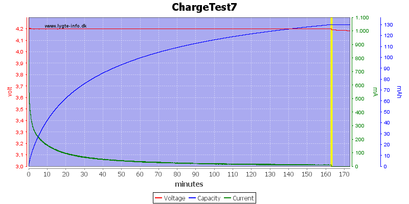
It looks nice enough, but is there something at the start?
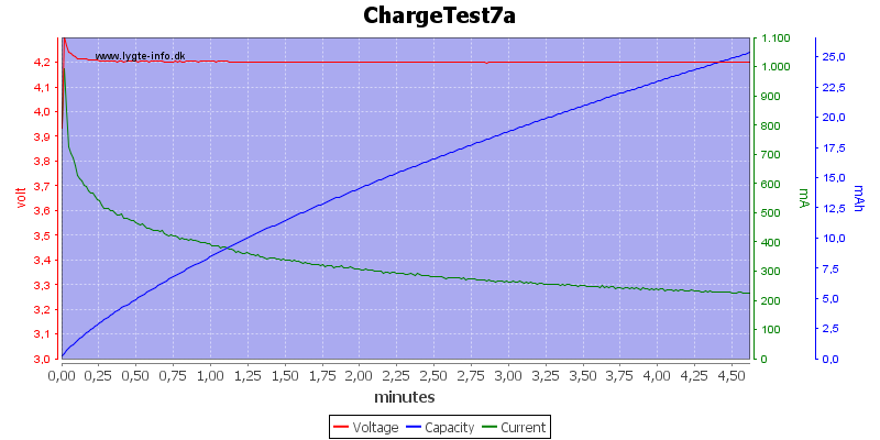
Zooming in on the start shows that the charger hits 4.3V for 1 second, not really a problem.
The charger is a constant current charger, it cannot do constant voltage, that is done in software. Usually regulation is within a mV, but if the voltage raises fast it need some time to adjust the current and may go a bit to high.
Current regulation is fast, but voltage regulation is slow. I will try to improve the speed slightly of the voltage regulation.
How about CC - CV - TC? The “UPS way” of charging a Lead-Acid battery.
I.e.
1. CC at 0.1C
2. CV at 14.4V, until current drops to 0.01C
3. CV at 13.5V indefinitely (until user unplugs the battery/charger)
Where would I (or other people) use it? The charger can only work up to about 4.5V.
LiIon has fairly low self discharge and there is no point in keeping a maintain charge, except if you want it to be connected to mains for years (i.e. UPS), but then again it is not the ideal way for LiIon.
Oops, I missed this spec. My bad. :zipper_mouth_face: