I have a Brinyte BR3000 host, (purchased from Chicago X, he has at least one or two of everything and wraps it like it will be dragged on a rope, to it's new destination, but it gets ther safe. Thank goodness for Chicago X
  !).
!).
I am going to turm it into a triple XM-L T6 light. I thought I would show some photos and talk about what I am going to to and my thoughts on the host.
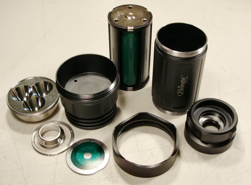
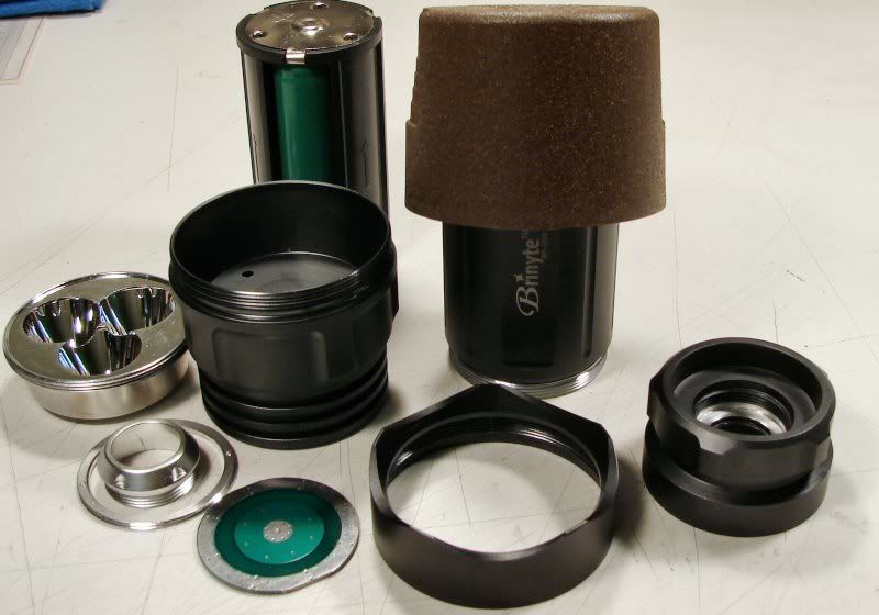
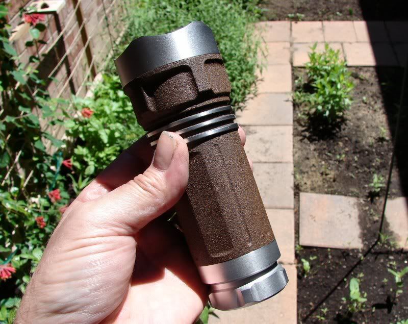
Here's the light torn apart. Overall the finish (ano) seems well done, but the threads are sub-standard for the original asking price of the light. Of course I don't like the Brinyte logo or that stupid outline of the battery showing all of us idiots that plus goes in first, so that will change. Overall I think it's a mediocre light. Not great, not terrible, but from what I read, the finished lights were terrible worknamship. Even worse than I normally do when I mess up leds and drivers! That's pretty bad!
The new color of the body will be a brown textured paint.
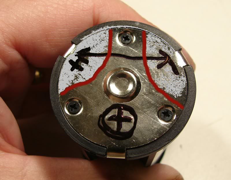
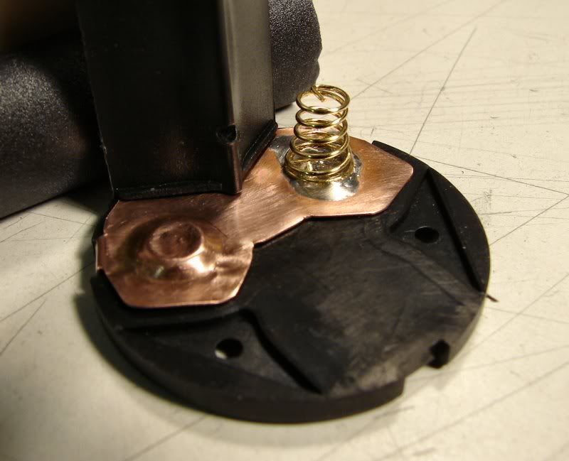
The battery holder needs to be changed from Parallel to Series. I will need to strip it down and rework it. The + that is circled will be the + for the holder. The red lines show how the copper plate will be replaced with the stock one. The gray areas mean metal will not be there. The arrow and +/- mean that those contacts need to be together, so that the holder will be in series. I will need to make a plate inside going across those two spots.
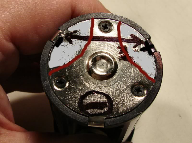
The same for the bottom - contact plate, as I already described above.
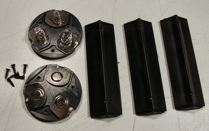
This holder is really made very well. I know it's just plated steel and plated springs, but aside from that, the holder is made well. Screws hold the top and bottom plates to the uprights and they are made from a higher quality plastic than the normal cheapie holders. This holder will take more heat than the cheap ones and will not warp either.
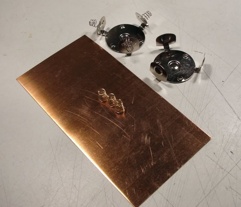
I will be using copper sheet for the new contact plates and gold plated springs. It should be a better holder when I am done and it will be series using three 4/3AF NiMH batteries. (same size as 18650)
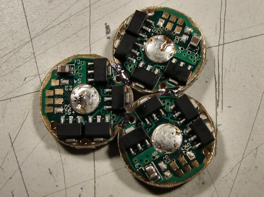
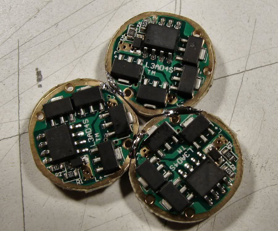
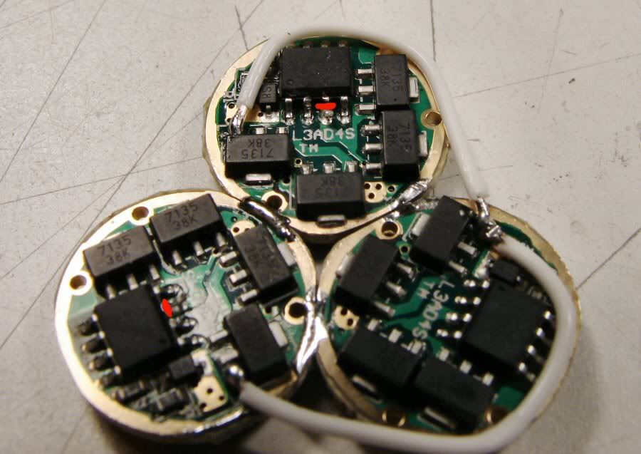
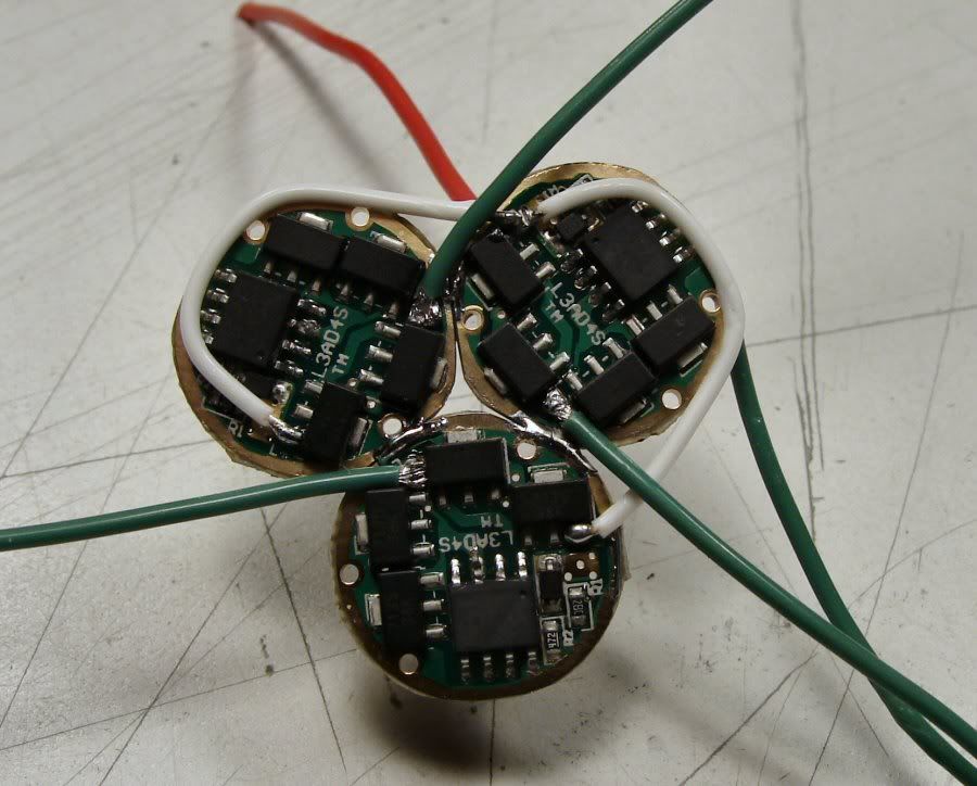
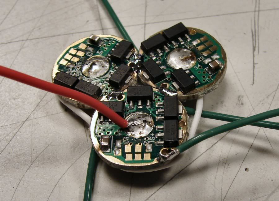
As the note says, I will use three XM-L T6 leds and three 8x7135 drivers using TechJunkies wiring schematic.
----------------------------------------------------------------------------------------
More on the battery holder mod.
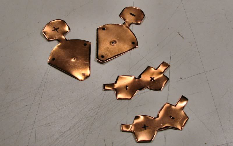
The copper replacement contacts are cut and ready for forming.
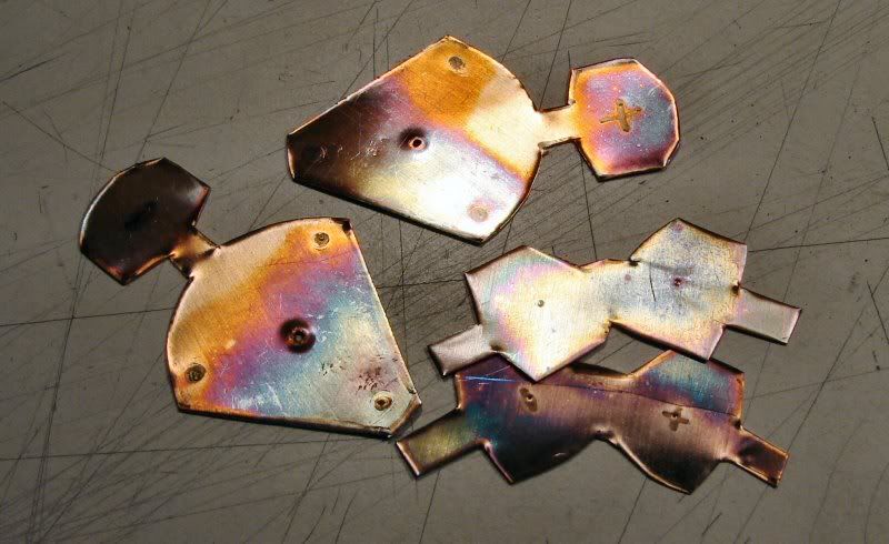
First they have to be heat treated to soften them. I heat them until they appear silvery looking under the flame of the torch. When they cool you can see the discoloration from the heat.
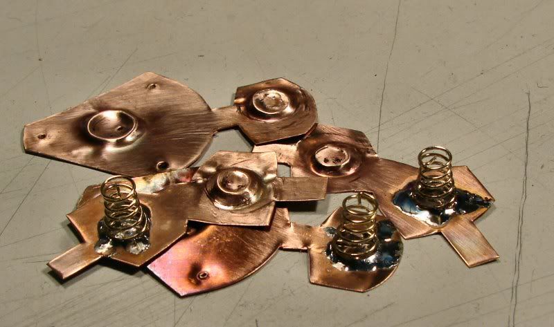
I form the positive cups, by using small sockets and hammer the copper on soft wood to form the shape. I also soldered the gold springs in place. Next is final shaping, straightening and fitting to the plastic frame, as well as cleaning with steel wool, to remove the discoloration.
Making sure the contacts fit.
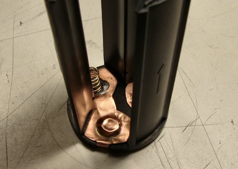
One end finished.
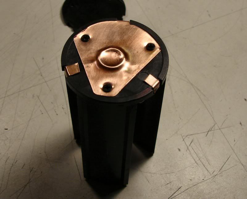
and the other side.
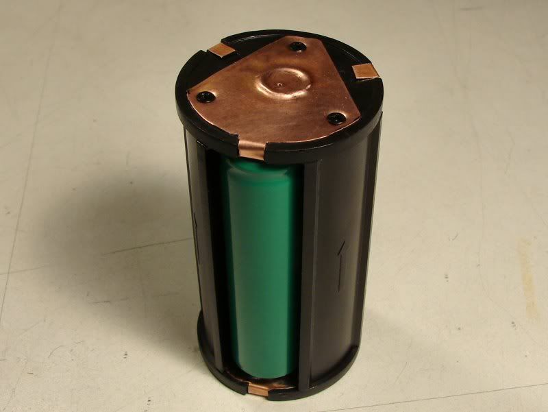
Battery holder completed and it reads 3.95vdc. It's still a Hack job, no matter how you look at it, but it should cut down on the battery holder resistance.
--------------------------------------------------------------------------------------------------
Paint & Polish is Done!
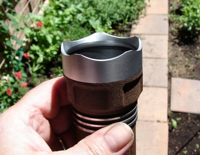
I like the Brown Textured paint! This took a while. I painted the body and head, no problem. I removed the paint from the rings on the head, no problem. I stripped the bezel and tailcap, no problem, well maybe there is a problem. It's hard to describe, but the stripped parts looked like it's a different type of Aluminum. It had (and still does) have a whitish cast to it, that does not look good when polished. It looked "funky".
So... I thought I would try painting them with black. Nope, that looked really bad. Then I had to figure out how to strip the paint, Ok, I will just soak them in paint thinner, since the paint is freshly applied. Nope, no way, it didn't even phase that paint. Well, then I will try the degreaser that cuts Ano so well. Nope, didn't phase it one bit. I thought, hey this is some tough paint!
Then I remembered the Acetone on the lower shelf! Acetone, I have never used it for stripping paint. I use to clean parts. Man Oh Man, does it ever work! I put the parts in a plastic tub and I am not joking (I was watching the clock), it took all of 15 Seconds to lift the paint off completely! It didn't dissolve the paint, but the paint just lifted off in one piece. If you have ever seen that paint on water stuff (hydrographics), that's what it looked like. The paint lifted off as one sheet and I just pulled the parts out, clean as a whistle. Unbelievable!
Acetone is Nasty - Nastytone... So if you ever use it - Gloves, Respirator, Open air environment, eye protection, Be Careful. It's just plain nasty. I poured the Acetone back in the can and just wiped the paint off the bottom of the tub with a paper towel. One nice thing about Acetone is, it evaporates really fast, so the paper towel was dry within a minute.
Anyhow, the finished light ended up being brown, with "brushed aluminum". I just used steel wool on the bare metal and it looks pretty good.
------------------------------------------------------------------------------------------------
Finally Finished!
Here's some photos of the rest of the build:
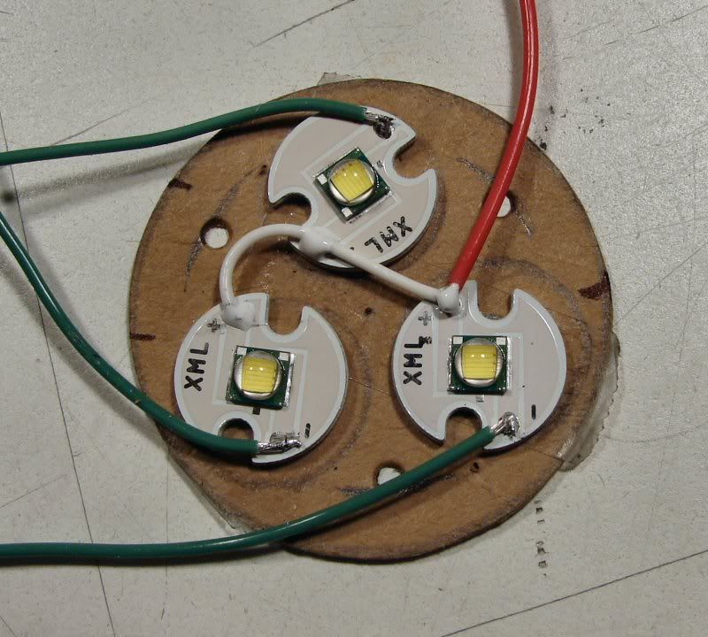
I decided way before the emitters arrived, that I could never solder them, once they were in place. I came up with using a cardboard jig. I put double sided tape on it and stuck the emitters to the reflector bottom. Then I stuck them to the cardboard and removed the reflector. This allowed me to solder everything right here in the open. So much easier, in the long run!
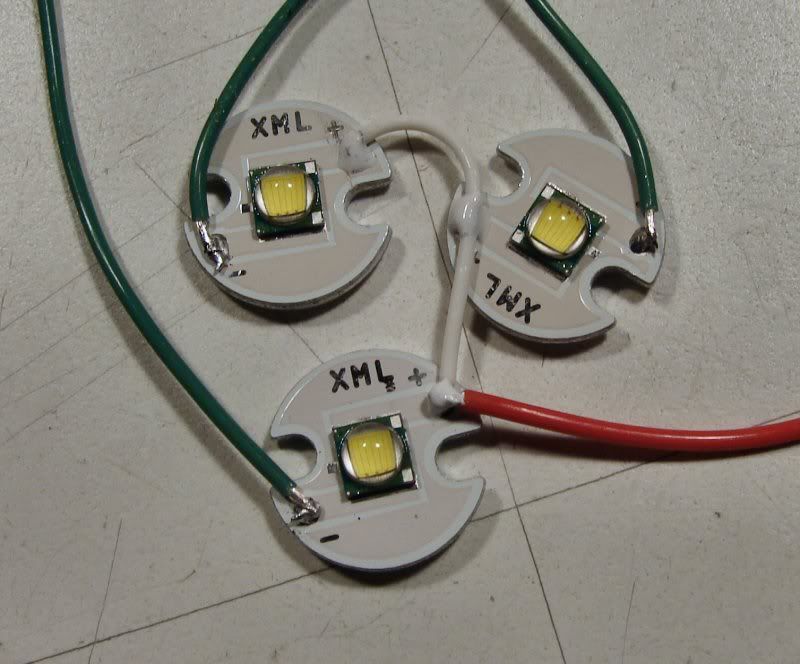
I used solid wire (white wire) in between the emitters and it keeps the shape once the cardboard is removed. Now I can place the whole thing into the head of the light and use the reflector to center it all, while the Arctic Alumina dries.
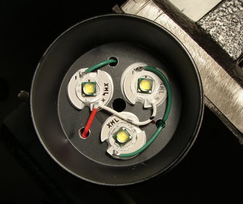
Emitters are in place.
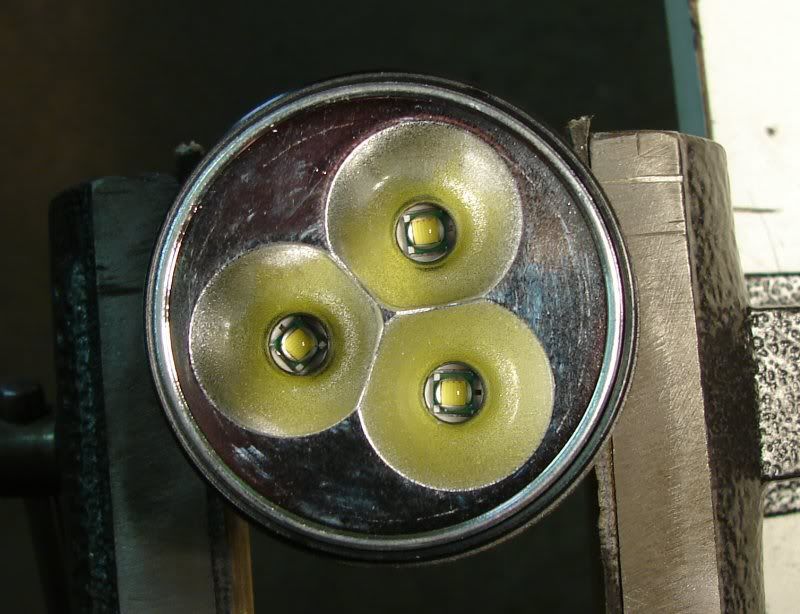
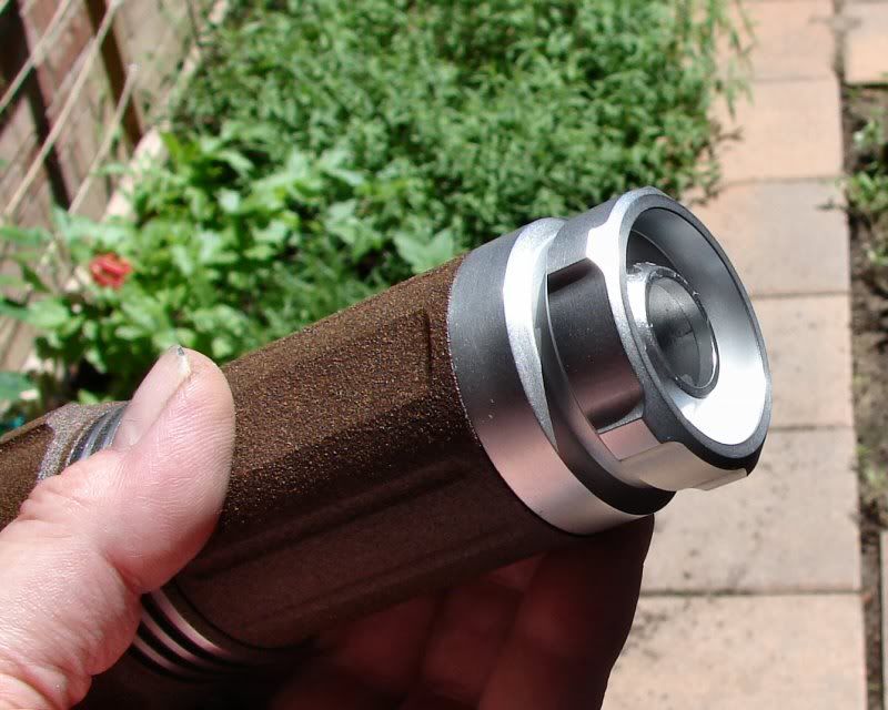
Here's how it looks with the reflector in place.
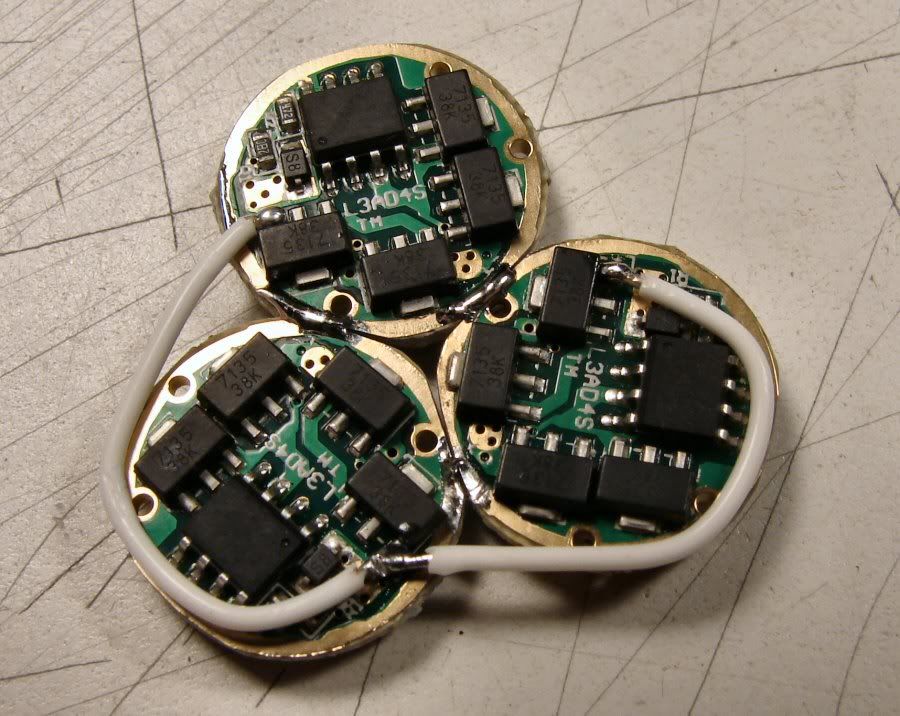
Look in Post #18, for the datails of the Driver assembly.
-----------------------------------------------------------------------------------------------------------------
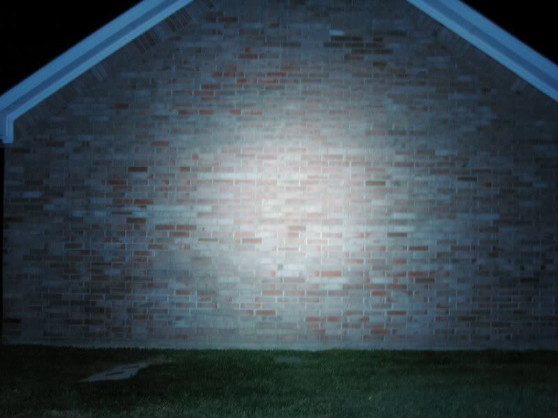
Beam Shots.
I am Not a beam shot guy. I can never show just how bright these lights are. My camera can't do long exposures and it sucks. Here's the best I can do and I can only say that these shots only show about HALF the brightness of this thing! It's a "wall of light" and it still reaches out to 100 yards and lights up an entire area at that distance! It's absolutely amazing just how bright this thing is!
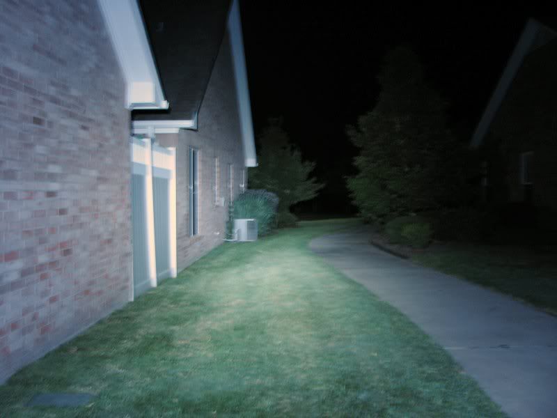
Even thought the photo does not show it, this thing lighted up this area much brighter than daylight and it lit up the trees in the background, to where I could plainly see the detail! The background trees are about 40-50 yards away!
I've done other shots of the pond, but this thing lit up the whole bank of trees on the other side and in reality it's about twice as bright as this photo. You can see that I need a new camera, but that's never going to happen.
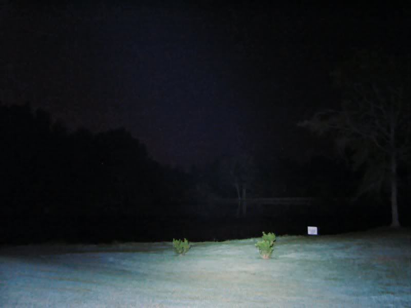
This one shows it a little better. That light made the whole end of the pond (the dam end and that's what I said when I turned it on, Damn! that's bright). I could clearly make out everything on the dam end of the pond and in the trees surrounding it. As I say, it's about twice as bright as the photo shows.
I sure as hell would not want to ever shine this thing in someone's eyes, unless I wanted to do some kind of permanent damage. It's way too bright for me to ever use and I don't think I will ever do another 3up. It's ridiculous and just not my type of light, but Damn it's bright!