Dude, you have screws right there. They both thread down into the head and are grounded. Take your negative wire and strip the end about 3/8 and make a loop. Put the loop on top of that fiber washer on the top so the screw head squishes the wire. That will ground it out. If the wire strands are thin there should be no way they will get pushed through that washer. I suggest a loop so you get even pressure all the way around the screw head.
If I remember correctly the D4 driver sits on an anodized rim and threads are anodized as well
Its very likely even the screws have no ground
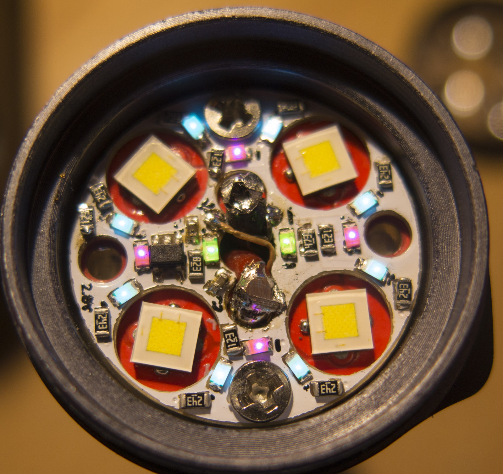
I think this is the newer version D4 head that ttylamg has.

Pic from Beastlykings.
It does look like the head was anodized and then they machined the flat shelf area. This is why the divots around the screw holes are dark. I would check if the screws are grounded. Maybe the threads cut through a bit and are touching bare metal.
One thing you might try is scrape off the anodizing between the head and the mcpcb, then take the wire end, strip it, ball it up and try to wedge it against the bare metal between the head and the mcpcb. If you loosen those anti rotation screws you might be able to move the mcpcb to one side, push the bare wire into the gap and then put the screws back in which should squeeze the wire and hold it securely into place.
Short of that, you might have to bite the bullet and remove the driver so that you can solder it into place.
You not gonna say how you got ground connected? We are in suspense. ![]()
Oh, sure I will be happy to share. So I scraped the thread from body tube to head like a lot, and for extra assurance I penciled the head ground contact from mcpcb to head as well. Tested scraping a bit of hidden area on head inside near the lens and put it all back together to make sure it was reading 3.7 red lead and head. Then I started scraping head near the lens post closest to aux . Ran a short lead from aux to it. (You can see how I did the red and+ and L in earlier post)
This sounded easy but in reality it took a lot of trial and scraping. I also found the star near the lens post was bare. When I put the - lead there it would accidentally complete and bypass the control circuit and light the flashlight! I almost just solder it without testing it. That would’ve sucked. At the end I scraped it a bit higher and didn’t solder the aux board to anything (except the leads). The sequence of this mattered a lot as there were many small things I’ve done wrong and redo. If anyone wants a detailed instruction on how to do this exactly I can re-write this entire post to be clear.
So both screws were insulated from ground?
I’m still not sure where you found the ground, near your red arrows? Does the optic leg squish the wire end down to the bare shelf?
i didn’t use the screws to ground, and didn’t even reinstall one of them since it was touching an aux led. I also suspect they might not be grounded anyway. I found the head housing completely isolated. I scraped the heck out of the threads where the body meet the head, testing multiple times to finally get grounding to the head (i scrapped else where near the top), then scrapped roughly where i drew the red arrow for the aux ground. You need to be careful not to do it too low, as I said the star is bare near there too. You don’t want to end up grounding the star.
the optic leg doesn’t squish the wire (I originally had it routed that way, but it was shorting the star), I end up just having it get pinched by the aux board to touch the head housing. If this is not clear I can do some sketches showing what i mean after the weekend.
Does the D4 have a one piece head or a threaded in pill?
1 piece head
driver is kind of press fit in
I have destroyed on some parts on drivers the diode or resistor with a bolt hammering the PCB out through the middle hole
replacing them fix the driver easily
See, that’s the beauty. I wouldn’t know, because I didn’t remove it. The mcpcb toward the + terminal had nothing to holding it down, and I wouldn’t know how it would come out
For a German Customer I built a rainbow Aux for MF01
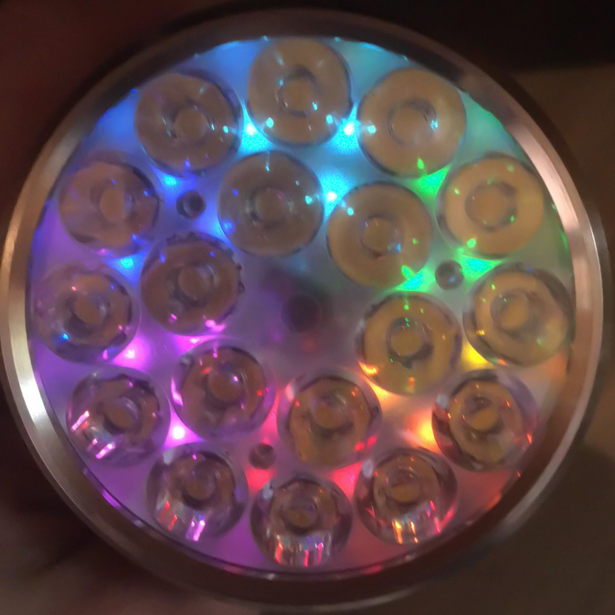
Outer ring of green full battery indicators off in picture
![]() Wow!
Wow!
Now I know what my MF01 needs. ![]()
It looks much better as the rainbow in my D4 because of the larger space and more LEDs.
Bump for Manker E14, may be able to reuse old D4 boards
depends who wants to test, but newer D4 boards use specially shaped holes with the rotated LEDs
but old stock D4 have 4 round holes, but less functions
Lexel, good to see you back! I was getting worried. ![]()
Here’s a pic of the E14 III from my review

Based on Lexel’s D4 pic of the original boards from Post #11, it looks like the wires and screws are in different locations. Doesn’t look like it’ll work, unfortunately.
After having made one for my TO50R, I’m tempted to try one for the E14 III. I’ve come to rather like the aux boards. KawiBoy1428 has said the driver is glued in, so that’d be fun… ![]()
seems those screws screw any design likely up, but then more space on the outer rim make it up
Is there a way to get an MF01 aux board at this time? I’m happy to buy second hand, prototypes, even unpopulated PCBs, I’m also fine having PCBs made if the design specs are open sourced somewhere.
Lexel has not been on this forum for over a year.