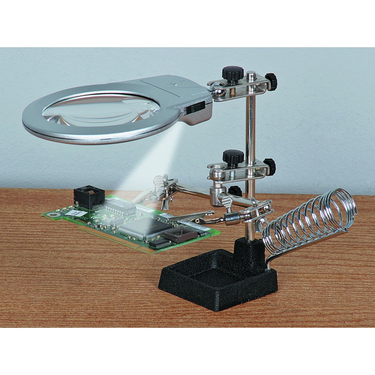
That’s where a magnifying glass and some glasses become necessary. My short distance vision started to suck a couple years ago, but various strengths of reading glasses and some “helping hands” kept me in the modding game.
I gave my LT1 permanent aux leds. I first was tempted to go red or orange, preventing melatonin suppression you know when using the LT1 as night light . But I wanted the aux leds so dim that any physiological effect is ruled out anyway, so I decided on pretty 485nm leds, which at this very low current looks to be about 500nm (out of the range of melatonin suppression after all )
I picked up batt-minus at the ground ring near the USB-socket, soldered an oldschool through-hole 39 kOhm resistor in a via, and then soldered the white wire to that resistor (covered the solder joint with some kapton tape).
I scratched the soldermask off 4 bits of the led+ trace and thus created solder pads for the plus-side of the aux leds. The minus sides of the aux leds were interconnected with a thin wire. The end of that wire was soldered on a pad scratched into a trace that connects to some thermal pads of the 2700K main leds (they are electrically connected to nothing so can be used freely), just to have a solid place to go to. Another pad scratched in that same trace was used to solder the white wire to.
39 kOhm is a very high resistor so the aux leds are really really dim, only well visible when it is pitch-black. The first picture is an impression of the colour, the second picture is about how dim it really is, look at it in the dark to get the idea. The switch leds are at low setting btw.
The aux leds should drain the batteries in about 35 years.
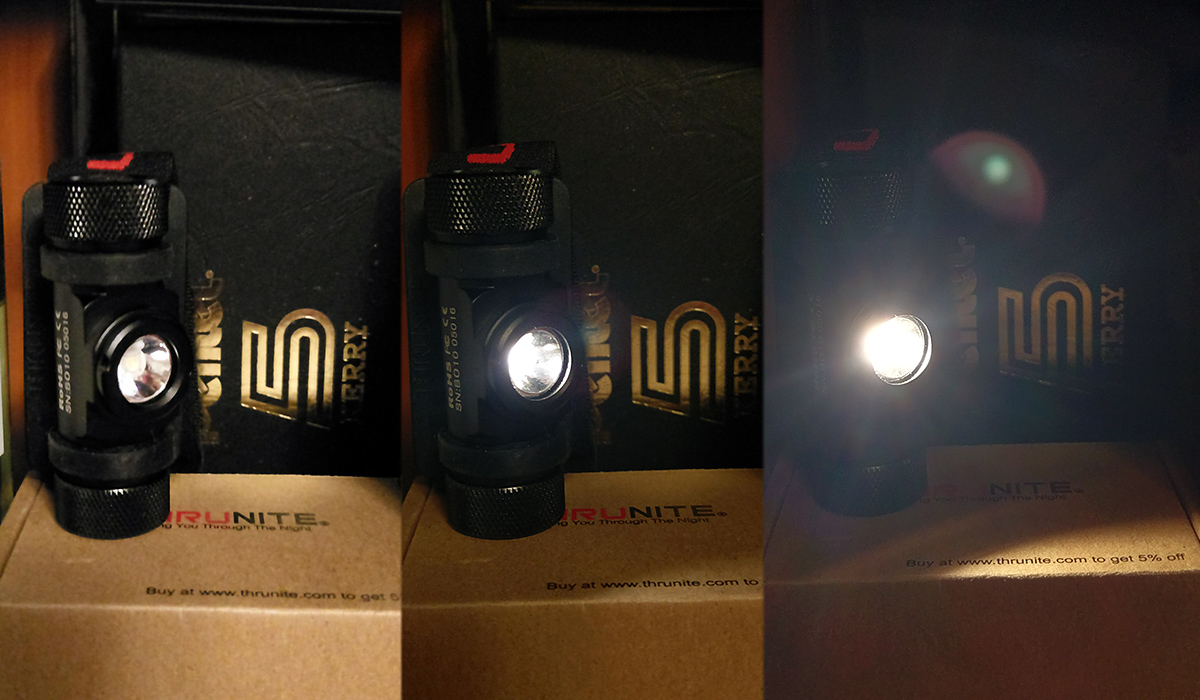
A BLF friend of mine did an emitter swap for me. The Thrunite TH-20 is a great light, simple head lamp for a really good price. Excellent quality. Only the stock emitter is a bit too green/yellow. Had a 219B 9050 sw30 installed. Now it’s wonderfully warm. Direct comparison to a cool white emitter makes it look so incandescent.
So it’s not as bright as it was before, but it’s only a marginal drop. This kind of headlamp is meant for near-field tasks anyway. Headband is very comfortable. I’m going to be using this for a lot of night time work around the home & car.
My C01S driver suddenly failed and I didn’t want to pay $6 for a replacement high-low driver so I made my own 10440 driver for 30 cents. It’s running biscotti with with configurable modes, I currently use L - H - L - H - 4 bar battcheck.
Very cool. I really admire your talent. If I could do half of what you’re capable of, I’d be making all kinds of sci-fi “devices” that just happen to have emitters for flashlight use.
Really nice job, would somebody knowledgeable explain what is going on in this mod :D… for serious I am interested in some explanation or picture description :).
Nicely done on that C01S fix! Considering how tiny this thing is, that’s very impressive.
It looks like the stock board was stripped and the main components of a “typical” linear driver have been fixed on top of it (with an insulating layer in between). A attiny13a to run the show (the 8 leg chip), a single AMC7135 for current regulation (the second largest black chip), a capacitor to help smooth out the incoming current for the attiny13a (usually called a decoupling or bypass capacitor, it’s the small tan-colored? chip), and two resistors (small, black) that form a voltage divider so that the attiny13a can read the battery voltage.
That’s all the components you’d find on a Nanjg105C / Qlite driver. But instead of 4-8 of the AMC7135 regulators (350 or 380mA each), there’s one. At ~350 mA, he’d probably see 120 or so lumens. BTW, this makes the light 10440 only, no AAA.
A quick and dirty one. I’ve been meaning to do this to a light for ages but just not to this light. I shrink wrapped my D25c ti. It probably won’t last long.
Yes. 7135’s have three pins: VDD (positive input), Ground, and Out (low level / negative output). When voltage is supplied to VDD, the Ground is allow to flow to Out* (restricted to ~350mA). When voltage is removed from VDD, current stops flowing. By pulsing VDD (via PWM) you can vary the effective (not actual) current being sent to the LED. If you use the MCU (attiny13a in this case) to supply a 10% duty cycle PWM signal, the 7135 is enabled for 10% of the time. Over the course of a second, you’d get 350mA for 0.1 second followed by 0.9 second of no current flow. Of course we use a much faster frequency than 1 Hz (Hz is cycles per second)… more like 8 - 16 kHz. Because of it switching so fast, our eyes usually cannot detect the on-off switching (unless a lower frequency is used) and we just see the average state of the LED, so we see it as if 35mA had been constantly applied to the LED.
I’m sure there are some nuances here that I may have mis-stated, but that’s the gist of it.