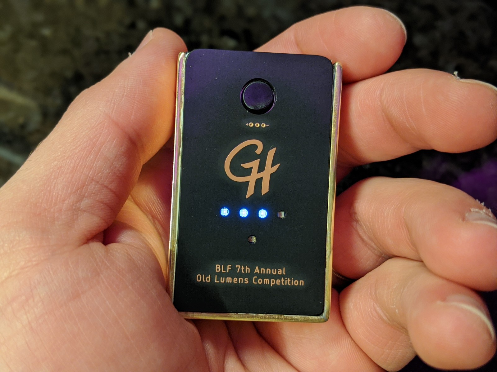
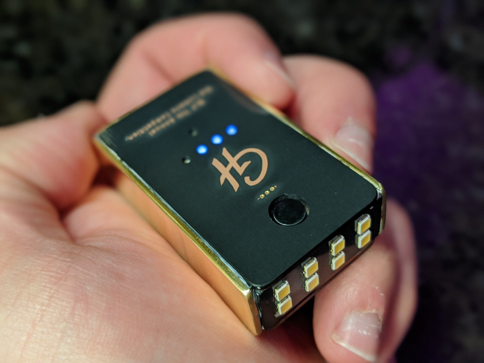
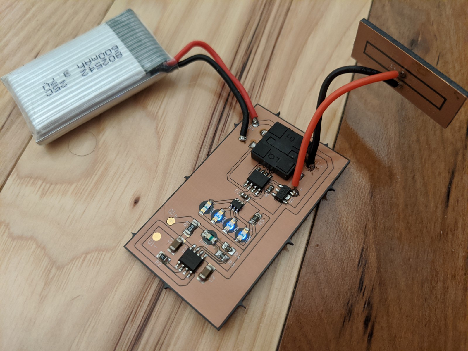
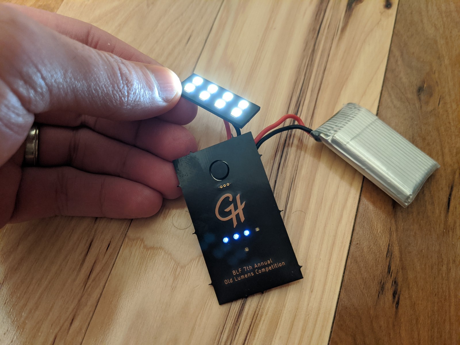
2020-02-11 Update: Electronics mostly assembled and tested. Details in Post 45
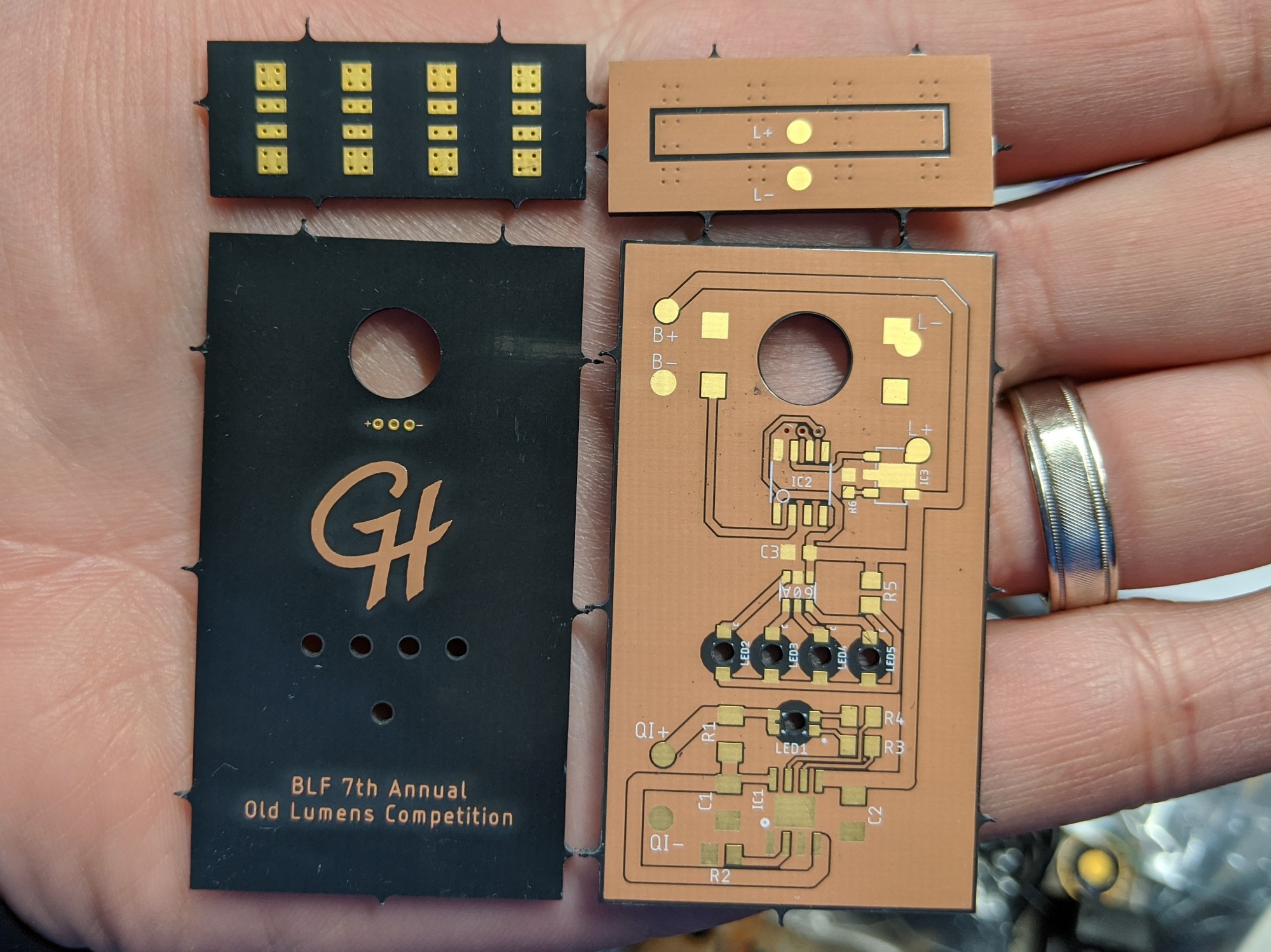
2020-01-30 Update: PCBs received
2020-01-14 Update: PCBs ordered, parts received
PCBs have been created and ordered (using Oshpark’s After Dark service)
Qi receiver, TP4056, primary LEDs, and reverse-mount LEDs have been received
Brass strips have been picked up from my local Ace Hardware (who knew they have a nice assortment of brass and aluminum stock from K&S?)
Updated model created that’s even more compact
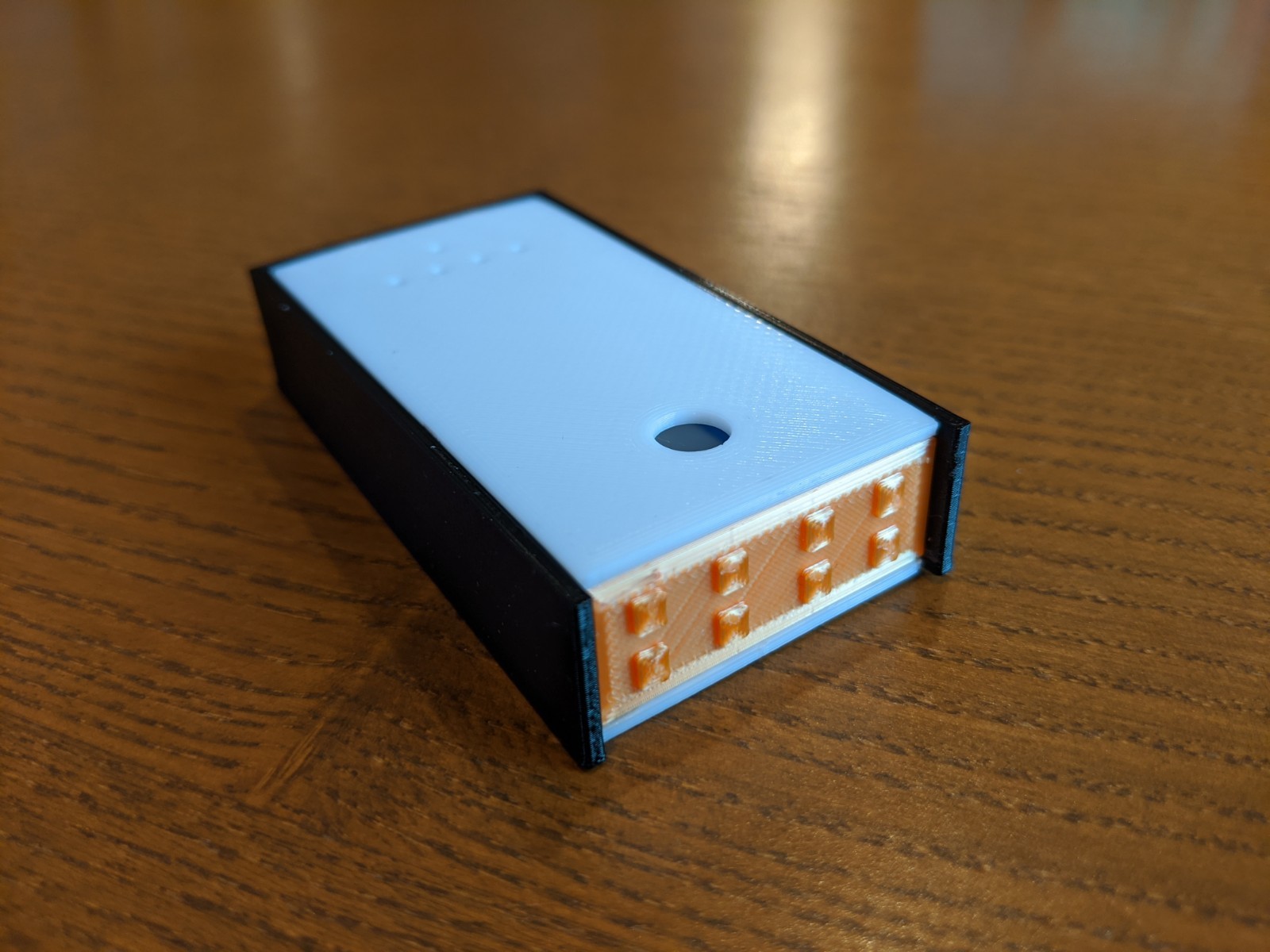
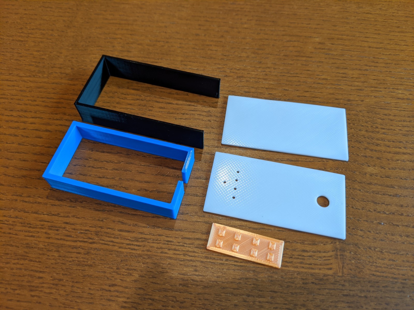
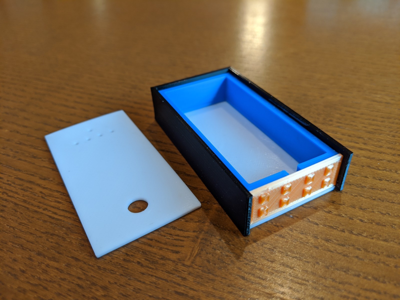
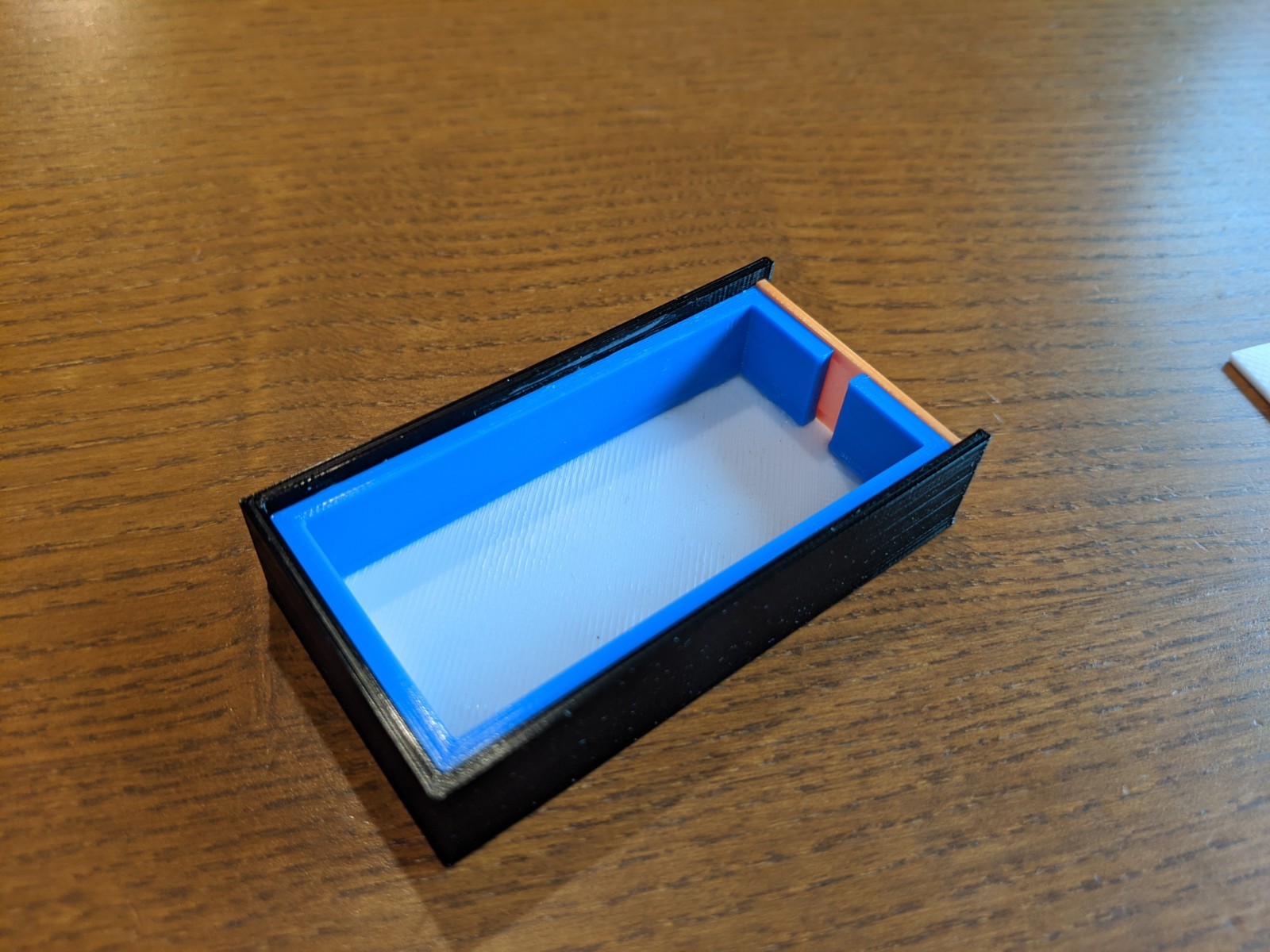
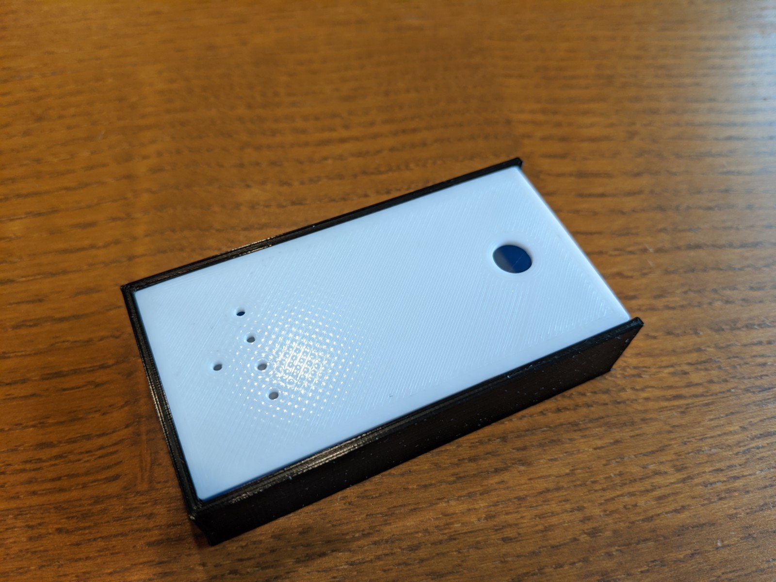
2019-12-30 Update: I decided to make a model to confirm fitment and sizing. Details in post 21.No printed parts will be used in the build, this isa mock-up only!
2019-12-11 Update: (some) parts ordered
I think I’m getting the electronics side of things refined, though I’m still mulling over the exterior.
I ordered a few TP4056 charging boards that I’ll scavenge the parts off of and solder directly to my main board (for space savings and so I can integrate the charging status LEDs)
While browsing for the TP4056 boards, I ran across this interesting battery status module and was able to identify the IC it uses (HM1160). I was planning on using the ATtiny to drive some battery status LEDs, but this will be a nice discrete option that will find it’s way into other things (illuminated tailcaps using it coming soon!).
Lastly, I also ordered some 150mA 4000K 2835 LEDs. I used the 60mA version in last year’s flip lantern and they seemed to be pretty good. I’ll use an array of them in the front for a bunch of floody light.
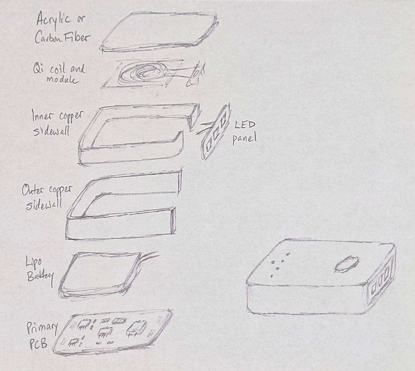
I’m still debating about the backplate to which the Qi coil will mount. Carbon fiber would look cool. But I’m also thinking about a smoked (transparent black) acrylic/plexiglass so that you can see the coil.
2019-12-04 Update: General Ideas
I’ll go ahead and throw out some general musings that I’m rolling around in my head:
General form factor will likely be akin to the Nitecore TIP / TUP… rectangular / blocky and small
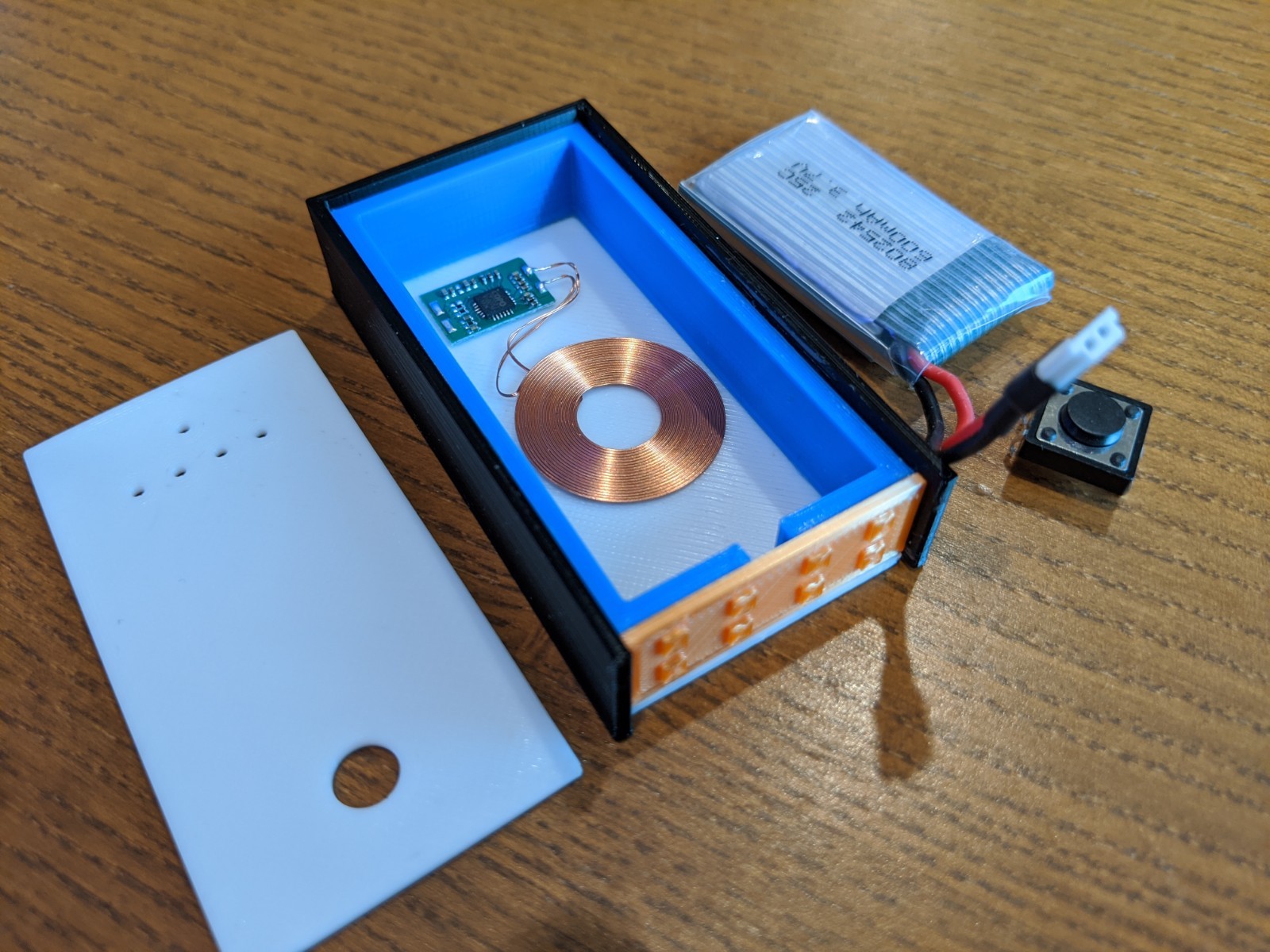
The light will be built around a 600mAh lipo that I have sitting around from ESP8266 / ESP32 projects
Since I’m using a built-in lipo battery, I’ll want onboard charging. I want to go USB-C since it’s newer and I want to support that factor (and that’s what my phone uses to charge), but I would really prefer the socket to be surface-mount without any thru-holes (due to aesthetics) and every USB-C socket I’ve seen uses thru-holes for support. So I’m on the fence between this and micro USB which appears that can be surface mounted without thru-holes. That, and the TP4056 boards are easier to come by in micro USB (there are some in type-C, but less common). I may have to get a board or two of each and just play around with them. I think I’m going to get a prefab TP4056 board, strip off the components, and put them directly onto my main board.
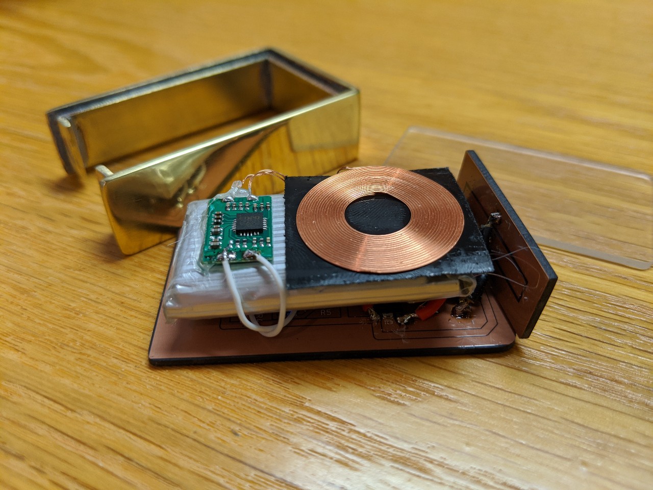
Another thought I had was that instead of messing around with the USB socket, perhaps embedding a QI wireless receiver coil (something like this)and wiring that directly to the TP4056… thereby eliminating the USB socket entirely. A little extra complexity, but it’d be pretty cool.
The shell of the light will likely be made from copper sheet / strips for a classy look… or maybe copper surround with carbon fiber sheet panel(s)? One of the side panels will likely be the main PCB itself - I’m thinking of using Oshpark’s new After Dark series, black and shiny copper.
I want the visible side of the PCB to be decorative with few, if any, traces visible. It will likely have programming pads (for UPDI), reverse-mount LEDs for indication and aux, and perhaps a touch-sensor pad. I’m really debating about mounting a thru-PCB tactile switch vs using a touch sensor for the switch. I feel like a touch sensor would be really cool, but then I’d need to lock it out all the time… I imagine the touch sensor would be accidentally activated in my pocket.
Looking forward to seeing what you come up with. I made my placeholder thread quite a while back, and still haven’t even started really brainstorming yet.
I’ll go ahead and throw out some general musings that I’m rolling around in my head:
General form factor will likely be akin to the Nitecore TIP / TUP… rectangular / blocky and small
The light will be built around a 600mAh lipo that I have sitting around from ESP8266 / ESP32 projects
Since I’m using a built-in lipo battery, I’ll want onboard charging. I want to go USB-C since it’s newer and I want to support that factor (and that’s what my phone uses to charge), but I would really prefer the socket to be surface-mount without any thru-holes (due to aesthetics) and every USB-C socket I’ve seen uses thru-holes for support. So I’m on the fence between this and micro USB which appears that can be surface mounted without thru-holes. That, and the TP4056 boards are easier to come by in micro USB (there are some in type-C, but less common). I may have to get a board or two of each and just play around with them. I think I’m going to get a prefab TP4056 board, strip off the components, and put them directly onto my main board.
Another thought I had was that instead of messing around with the USB socket, perhaps embedding a QI wireless receiver coil (something like this)and wiring that directly to the TP4056… thereby eliminating the USB socket entirely. A little extra complexity, but it’d be pretty cool.
The shell of the light will likely be made from copper sheet / strips for a classy look… or maybe copper surround with carbon fiber sheet panel(s)? One of the side panels will likely be the main PCB itself - I’m thinking of using Oshpark’s new After Dark series, black and shiny copper.
I want the visible side of the PCB to be decorative with few, if any, traces visible. It will likely have programming pads (for UPDI), reverse-mount LEDs for indication and aux, and perhaps a touch-sensor pad. I’m really debating about mounting a thru-PCB tactile switch vs using a touch sensor for the switch. I feel like a touch sensor would be really cool, but then I’d need to lock it out all the time… I imagine the touch sensor would be accidentally activated in my pocket.
It would be interesting to integrate the QI coil into the appearance of the light if you’re going with a black and copper motif. If you’re planning on more than minimal current you probably won’t be able to etch it on the PCB, but putting it on the other side of the light in clear epoxy might be cool.
I suppose I could make one side panel acrylic/plexi with the coil stuck to it from the inside so that it’s (1) protected and (2) visible. Interesting idea…
My thought with the two copper sidewalls is to have them layered with the inner being a couple millimeters shorter than the outer. That will create a shelf for the top and bottom panels to sit on. But getting the bends to match might be challenging. And I’m not sure how I’m going to stick everything together - solder the sidewalls together? Or use an adhesive? Kinda stuck on that part. Any advice is welcome!
I thought the double sidewall construction was going to end up with it being somekind of a battery using some sort of magical separator. :person_facepalming:
Seriously though, bending them together in a sandwich might be the way to get the bends to coincide. ???
What gauge metal?
Cut copper sheet to size and bend into the body shape, maybe use a forming block.
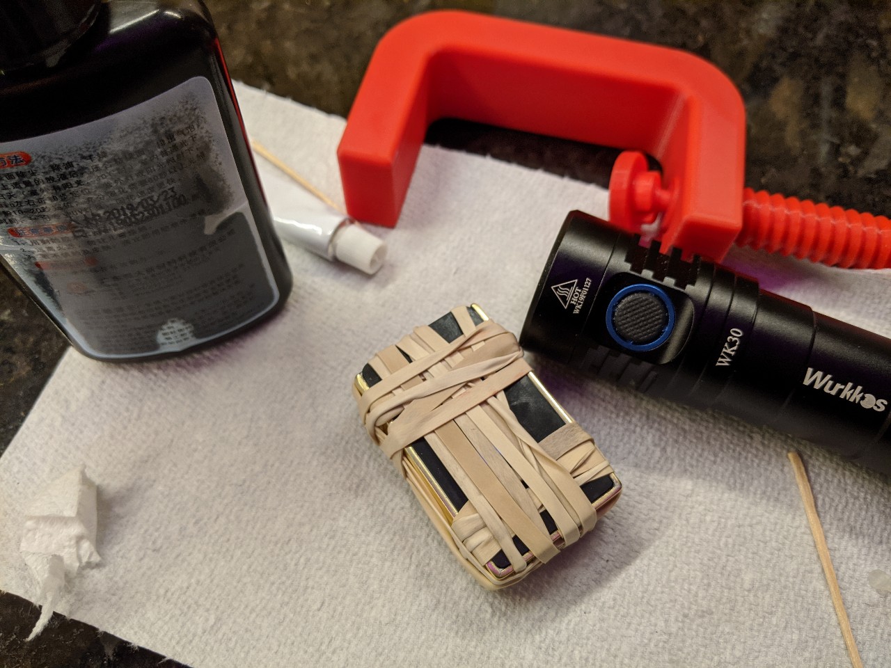
Clamp the inner copper to the outer when formed with a little solder paste and torch it.
Thanks for the input. Thats kinda what I’ve been thinking, CRX. As far as materials, I’m thinking of ordering some copper strips online. Probably something like 2mm x 15mm for the inner strip and 1mm x 18mm for the outer strip.