Good start ![]()
A bit sanding & polish when it’s all together can totally transform the look though I can see the potential now.
I like scavenging parts too.
![]()
subscribed. Nice build idea ![]()
Another terrific home made light in the making. I know if I tried to do what you are doing it woodn’t work. ![]()
Looks like a this style of a host would be nice for LedLink Athena, 45 or 60 mm version:
https://www.ledlink-optics.com/2018/05/31/v-cut-reflector-2-2-2/

But you’re clearly going in a different direction. ![]()
Yes! Eye of Sekhmet, that’s what you meant, right? ![]()
Yes, that has been an inspiration for a few builds ![]()
Run 1, 29 nov. Joule thief
After writing yesterday's post i started to think about several modifications/improvements in the way i might use the wood block but still have some unanswered question (mainly about the on/off switch and battery compartment) so i decided to work on the driver instead.
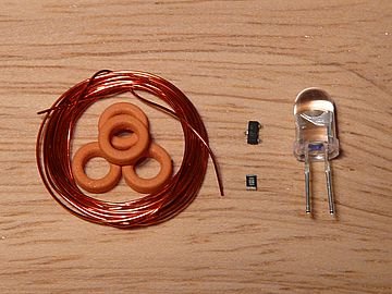
Minimal boost driver recipe :
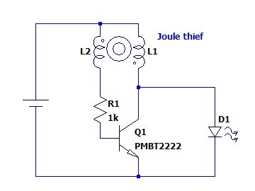
Take a length of enameled copper wire, the smallest toroid ferrite core you can get, one of these very nice 5mm high CRI 3400K led rngwn is selling plus a (small) npn transistor (PMBT2222 here) and a (even smaller) 1k resistor. Don't forget your schematic !
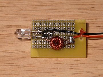
Assemble the parts on a piece of prototype PCB and, after verifying that everything is ok, switch the power on.
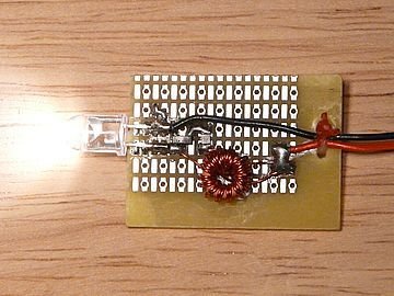
More about the joule thief after dinner ;)
Sweet idea! Great work there using the hands to think it out. ![]()
![]()
Thank you :)
The dinner was short but i had to do a lot of measurment so i am back only now !
I know that's a lot of numbers but i'm still searching a way to display them in a clear and nice graph (anyone knows how to have several secondary axis on a graph with Libreoffice Calc ?)
At first i measured a led alone, varying the curent and measuring the led voltage and light output and calculating the led efficiency :
| Supply curent (mA) |
Supply Voltage (V) | Supply Power (mW) | Light output (lm) | Led Efficiency (lm/W) |
| 1,0 | 2,59 | 2,7 | 0,3 | 129 |
| 2,0 | 2,62 | 5,3 | 0,7 | 128 |
| 3,0 | 2,64 | 7,9 | 1,0 | 126 |
| 4,1 | 2,66 | 10,8 | 1,3 | 125 |
| 5,0 | 2,68 | 13,4 | 1,6 | 123 |
| 6,0 | 2,69 | 16,2 | 2,0 | 122 |
| 8,0 | 2,72 | 21,8 | 2,6 | 119 |
| 10,0 | 2,74 | 27,5 | 3,2 | 116 |
| 12,0 | 2,76 | 33,1 | 3,8 | 114 |
| 15,0 | 2,79 | 42,0 | 4,6 | 111 |
| 20,0 | 2,84 | 56,8 | 6,0 | 106 |
| 25,0 | 2,88 | 72,0 | 7,3 | 102 |
Then i did the same kind of measurements on the driver + led and used the (roughly interpolated) led efficiency calculated in the previous table in order to obtain the driver efficiency :
| Supply Voltage (V) | Supply curent (mA) |
Supply Power (mW) | Light output (lm) | Total Efficiency (lm/W) |
Led Efficiency (lm/W) |
Driver Efficiency ( %) |
| 0,60 | 10,1 | 6,1 | 0,4 | 65 | 128 | 51 |
| 0,70 | 15,6 | 10,9 | 0,7 | 67 | 128 | 52 |
| 0,80 | 22,7 | 18,2 | 1,2 | 69 | 125 | 55 |
| 0,90 | 25,5 | 22,9 | 1,6 | 68 | 122 | 55 |
| 1,00 | 27,9 | 27,9 | 1,9 | 67 | 122 | 55 |
| 1,10 | 29,8 | 32,7 | 2,2 | 66 | 120 | 55 |
| 1,20 | 31,4 | 37,7 | 2,5 | 65 | 119 | 55 |
| 1,30 | 32,7 | 42,5 | 2,7 | 64 | 118 | 54 |
| 1,40 | 33,7 | 47,1 | 3,0 | 64 | 117 | 54 |
| 1,50 | 34,8 | 52,4 | 3,3 | 63 | 116 | 54 |
| 1,60 | 38,1 | 60,8 | 3,8 | 63 | 114 | 55 |
The efficiency is not too bad for a "wet finger" type of design but the light output is a bit low for my taste.
For comparison here are a few values that i measured on a warm white Sofirn C01 :
| Supply Voltage (V) | Supply curent (mA) |
Supply Power (mW) | Light output (lm) |
Total Efficiency (lm/W) |
| 1.0 | 38 | 38 | 3.0 | 80 |
| 1,5 | 54 | 81 | 5,5 | 68 |
So now i have two options :
1) Try to optimize the joule thief driver for more output (find a better transistor, test various parameter changes for the transformer)
2) Use a more conventional (and predictable) regulated boost driver
Well it's 03:15 so the only real option right now is to go to bed ...
Edit : corrected a few errors in the driver + led table
2nd edit : C01 data with more accurate test
I really like that driver out of a few simple items. ![]()
Run 1, 1 Dec. More tests
So i was balancing between trying to improve the joule thief or going for something more conventional ... and i eventually decided to keep the JT for this prototype.
Several, reasons :
- it's cool ;)
- i like to tinker with new things and i don't know that type of converter very much
- i usually prefer a regulated output on my flashlights but the "less volts, less output" works well for a small vampyr light
- there is plenty of time for improvements and tests before the end of the contest and i'll still be able to change my mind later and go with an other driver if i feel like it.
While i intent to do a lot of measurements on the driver for each modification i have to improve my test setup !
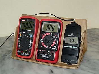
One thing i went through friday evening while doing the first tests set was that it was teddious to read the display of the two multimeters and the luxmeter because they were not leaning at the same angle so i improvised a "deluxe foldable measuring stand"
Ok let's work now !
I expected to be able to use a breadboard with traditional "through hole" component for easier components changes but the result was not very good (unstable measurements caused by bad connections) so i had to ruin the nice prototype with a lot of soldering/desoldering.
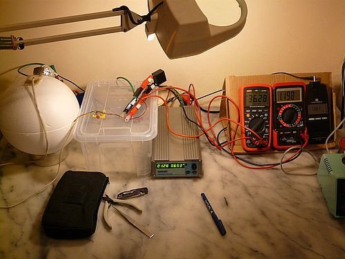
An other problem i met was i had no good way to fasten the protype to my integration sphere which caused some variations in the measured light output so i eventually soldered the led on his own board with a long wire running from the driver and taped the led board to the sphere so i was able to work on the driver without disturbing the led position.
Eventually i was able to obtain stable and repeatable readings and went through many tests series
The following picture shows the final setup :
Not much else to show for now as i tested several transformer configurations along with several resistor value during the weekend but this is still a work in progress and i don't want to frighten everyone whith pages full of numbers !
Run 1, 4 Dec. Still testing
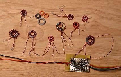
Just a quick update as i don't have anything new to show but a lot of boring tables full of numbers, a poor abused prototype and some weird 3 or 4 legged toroids
I am still working (maybe 20 hours total now) on the joule thief driver, trying to obtain the right tradeoff between output and efficiency, and i feel that i have gone as far as i could with the PMBT2222 so i have ordered a few other references that i expect to be better in that application (mainly higher gain and lower Vce-sat) and hope to receive them before the weekend !
Nice effort so far!
Gidday Hoop.
For once I have to agree with you. ![]()
Its all black magic to me.
Run 1, 7 Dec. Enough tests
Yesterday i received a few tansistors so i was able to do some (well ... a lot !) more tests in the evening/night.
The driver is not totally perfect but considering the very simple schematic i am pretty happy with the result and consider that i am done with that part !
More on the driver later but today i wanted to work on the "case".
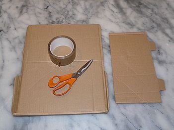
Hand tools :
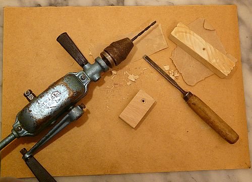
I cleaned and sanded the aluminum profile and wood block, drilled the led hole and carved the battery holder then assembled the whole thing.
Everything is fitting nicely
No screw required because the wood fits tightly in the aluminum profile
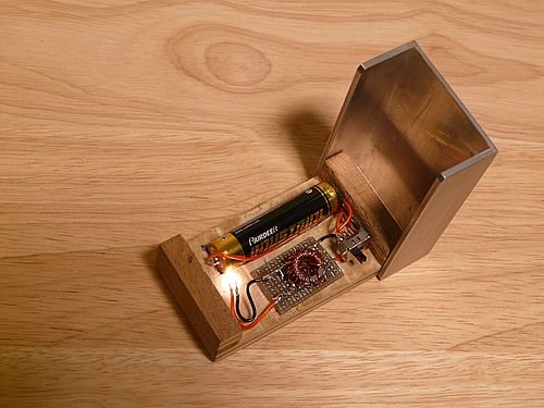
To do list :
- find a sliding switch and mount it on the side of the aluminum profile as the one on the picture is a small pcb switch with no mounting holes
- find some thin spring brass plates for the battery holder (for now the wires are soldered directly on the battery)
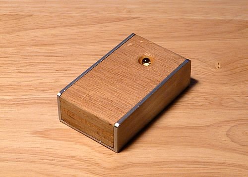
- find a good looking piece of hard wood as this one is too soft an easily scratched as can be seen of the last picture
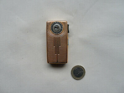
Random picture from internet of the Wonder mini that inspired this small build :
Wow! I haven’t seen a drill like that for a very long time, let alone use one to drill a hole. I am so spoiled by power tools, especially cordless ones.
Cool, love the use of manual tools for the hand made category ![]()
Purple heart is a tough and beautiful wood, I got two 3/4”x4”x12” pieces on Amazon for less than $15. It’d look fantastic in your light!
Excellent work there, very neat idea!
Run 1, 8 Dec. Driver update
As i promised yesterday here are some details about the joule thief driver.
The schematic is still the same with an added X7R 10uF decoupling capacitor at the input. I am not sure if it's really required here but i am used to always have at least some decoupling and it might help when the cell internal resistance increase.
My goal for this driver was :
- output at least 5 lm at 1.5V
- still about 3 lm at 1.0V
- at least 1 lm down to 0.7V
- overall efficiency better than 65 lm/W at maximum output, going higher for lower output
These goals were copied from the Sofirn C01 3200K which was my reference while designing this little light. The C01 driver use an integrated circuit with output regulation and the single transistor JT can't really compete with that but i tried my best and here are the results :
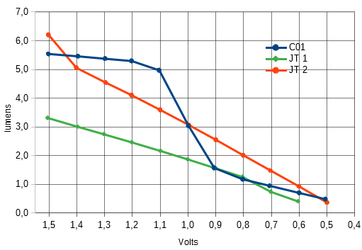
Light output (lm) vs input voltage (V) curve :
Efficiency (lm/W) vs light output (lm) curve :
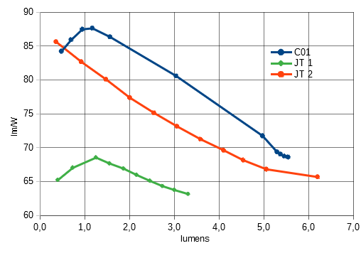
The green curves (JT 1) are from the first JT prorotype.
The orange curves (JT 2) are from the final JT prorotype.
The blue curves (C01) is from the Sofirn C01 3200K which was my reference while designing this little light.
As you can see, working on the JT allowed me to increase both of the light output and efficiency compared to the first prototype but there is a limit after which i wasn't able to increase efficiency without decreasing light output or vice-versa so i choose to keep the output.
Conclusion :
As can be seen on the curves the ouptut light goals are totally met and while i would have liked the efficiency to be a bit more on par with the C01 i am still very happy with the (about) 10% difference considering the very simple schematic !