My lumintop ti tool has the same switch I believe. First time I put batteries in it took a few minutes but since then it’s been perfect.
What happens when you pull the tailcap and use a wire to connect end of battery tube to battery negative?
If you still have hardly any difference between med and high then there may be something wrong with the driver, if it does show strong difference then the electronic switch is the culprit. At least you will know which is problem.
Mine acted somewhat same way till a Regular AAA primary reading 1.58v was inserted, then it charged up that tailcap real quick and we have been up and running just fine back on the Eneloops.
There probably is no stepup to switch voltage so you may need higher voltage one time to get it to spec.
Wish I had a Lithium AAA primary on hand to see how much brighter (if any) these lights get at 1.80 volts that these batteries usually start at when new.
HTH
Later,
Keith
I hope you get your curiosity satisfied.
Meanwhile, I hope you enjoy the light ![]()
I just put my Cu Tool w sw45k LED mod on my light meter and it gives 2.3 lumens, 20 lumens, and 80 lumens. The difference is obvious. This particular head is actually a lego of a Maratac head (dont believe their ridiculous lumen claims). I get similar outputs from a Tool Head…
When I got my last 219c Cu Tool, the maximum was 110 lumens. Thats more lumens than the 219b that I prefer. The 219c is greener.
My Cu Tool always has a battery in it, as it is my most used aaa light. I dont have any mode issues.
And I like that the eSwitch allows tailstanding.
Also curious. I hope it translates to lower parasitic drain. My equipment lacks the sensitivity to measure anything.
I agree that tailstands help offset the extra clicks needed with this design.
That either doesn’t make sense, or that’s the dumbest flashlight design I’ve heard. An hour to charge up a capacitor so the light will work properly?
Even a camera flash only takes a few seconds to charge up a capacitor, and it’s using it as the main light source!
It’s probably a small li-ion battery, not a capacitor.
Great idea, Keith. I found a wire, stripped the ends, and completed the circuit. And YES… now it was clear to me the difference between medium & high. I noticed even medium is brighter without the tail cap. So apparently there must be some kind of current regulation going on in the tail cap and mine is faulty. I installed the tail cap after this test, and now I can’t even get mode changes working properly again. It’s either some sort of medium, then a medium-high, which starts out a little dim while switch is still depressed then brightens a little upon release of button. No low. Hopefully the replacement will be OK.
Useful info, thanx Djozz
Even dumber design, then. You have to charge a separate lithium-ion battery in the tailcap, every time you change the “main” battery? I don’t believe it.
I think they’re faulty units. The “charge the tailcap capacitor” is a dumb excuse.
WTH? Nobody makes a flashlight electronic switch like that. Why would they? A li-ion battery would eventually require replacement, having far less lifespan than a capacitor. And a tiny li-ion battery sandwiched inside a tail switch certainly wouldn’t be user serviceable.
Here’s the abstract from Lumintop’s Energy storage type zero-power flashlight electronic switching circuit Chinese patent application:
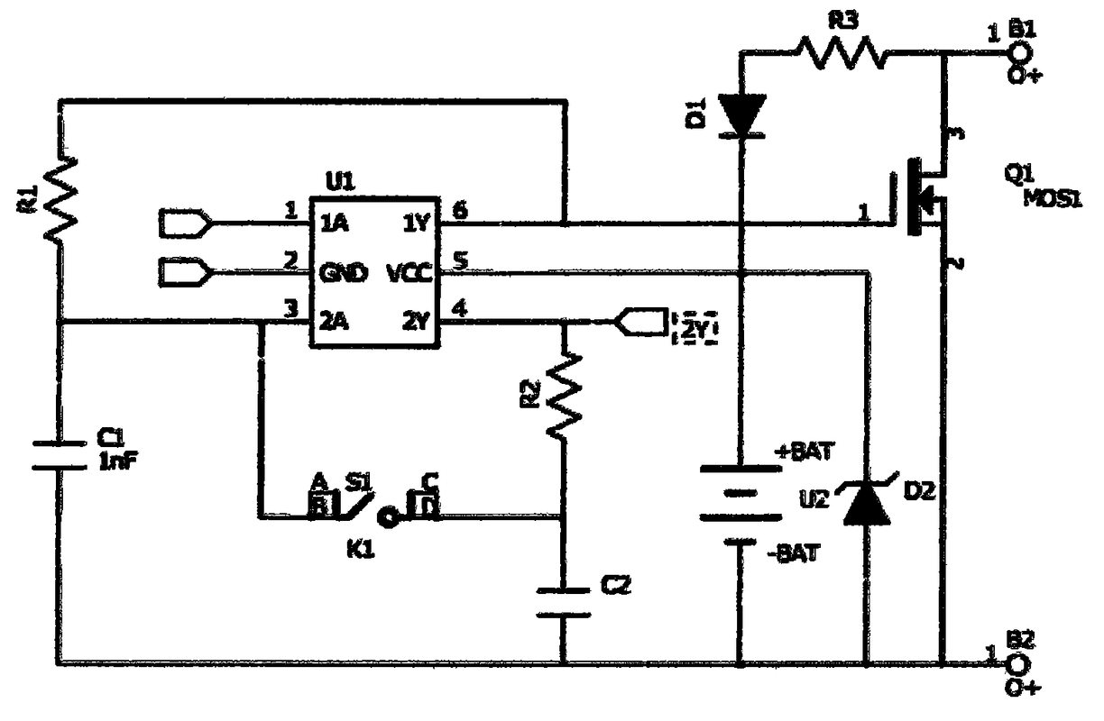
See paragraphs [0011] to [0014] if you understand electronics and can get past the machine translation.
EDIT: added pic from T18 in the other thread. Note there’s one more component on the other side of the board (the MOS?) that matches what I can see at the base of the spring on my MassDrop light.
^ What does this mean for the lay person who isn’t fluent in electronic circuit diagrams & components?
Copper is out of stock now. They have a notice link, and appear to expect to have more eventually.
it is actually a supercap
It means the capacitor in the switch needs to charge up for the modes to work. Once the cap is full, all the modes will switch.
If the cap is not loaded, the vessel cant make the quantum leap into hyperspace :student:
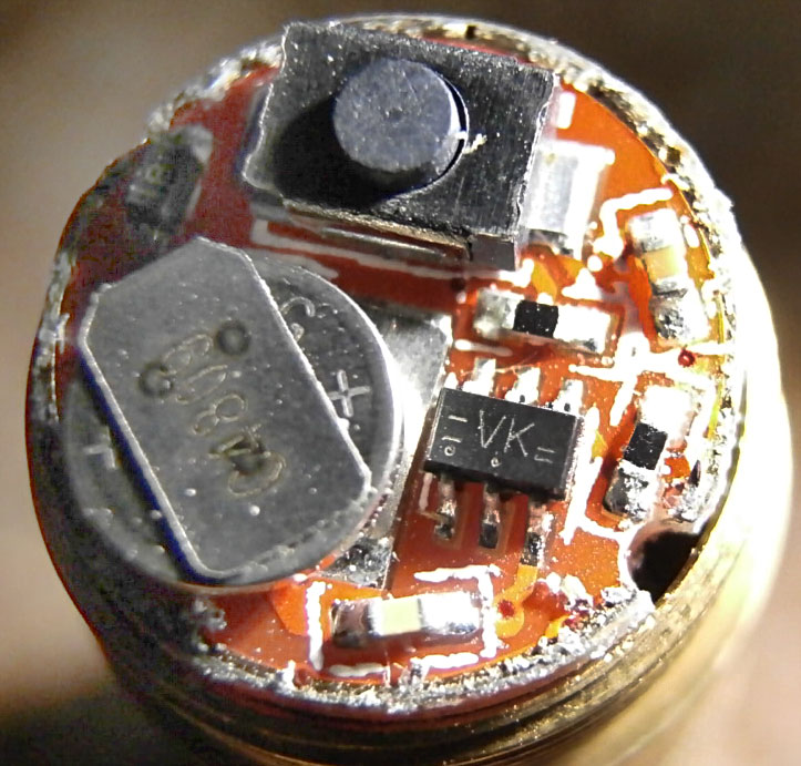
Thanks for the pointer. Here’s an interesting switch pic from that thread courtesy of T18 Available on BangGood now:ReyLight Custom-Lumintop Tool Ti AAA, L-M-H - #219 by T18
I see why it feels like the button is contacting the switch off center.
EDIT: I’ll add T18’s pic next to the schematic I extracted from the patent above for convenient comparison.
I just got my order for 10 Supercaps today from arrow electronics for building Loneoceans GFS16 FET switches. Ordered a few for spares.
The Seiko Supercaps are tiny and look just like a coin battery. Its only 4.8 mm in diameter.
https://www.arrow.com/en/products/xh414hg-iv01e/seiko-instruments-inc
It could be the same one used in these tool switches, I will check next time I take one apart.
.
Edit: I can confirm it is this exact SC, the Seiko XH414HG-IV01E.
if it’s a supercap then it should charge in seconds, not minutes
and something doesn’t make sense.
if it needs to be charged before use then it means there’s no battery inside?
and there was never a battery inside, no testing with a battery at all?
either that or the supercap lost it’s charge. so that means that thiswill just drain the battery all the time.
probably not a good idea to make switches like this
It works even when you dont understand why.
try one sometime…
Here is my eSwitch Cu Tool running an MLH head from a Maratac, w sw45k LED swap

Charge time will depend on how much current is provided. The current could be quite low if the supercapacitor is in series with a large resistor (e.g., R3 and the BAT in the patent schematic).
Yup.
Yup. A supercap is certainly not low self-discharge. It will continue to drain the battery as it continuously needs to be topped up with charge. You have maybe a month of shelf-life before your battery is drained by the supercap.
Yup. This stupid flashlight design.
Everyone else seems to be able to design lights with switches that can run off the main battery, and don’t need to be charged for an hour before you use it.
I still think the units must be faulty. I’m having a really difficult time believing anyone would design such a ridiculous switch.