You have to eat?
Nice work Don. ![]()
I did a little more on this today while I waited for a couple of little things for the other project to arrive.
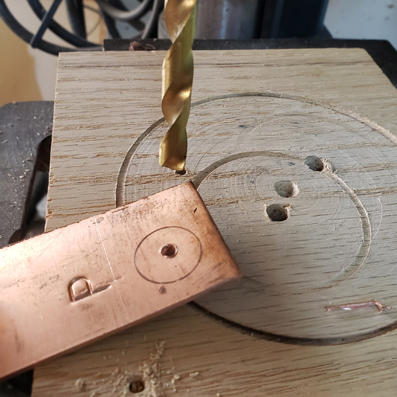
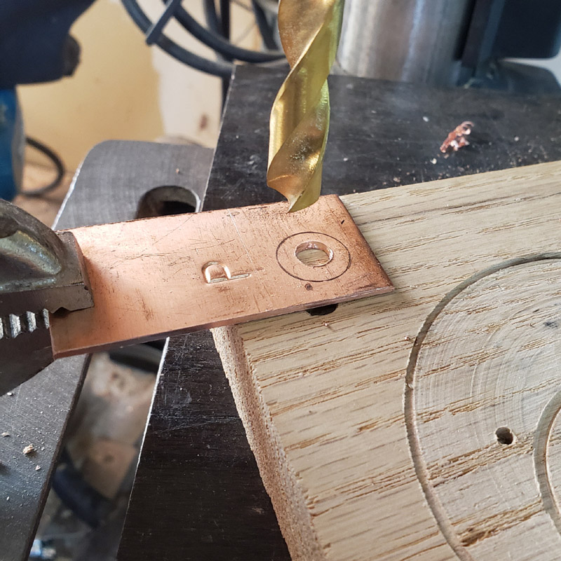
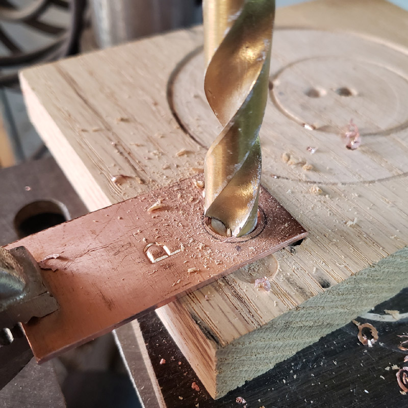
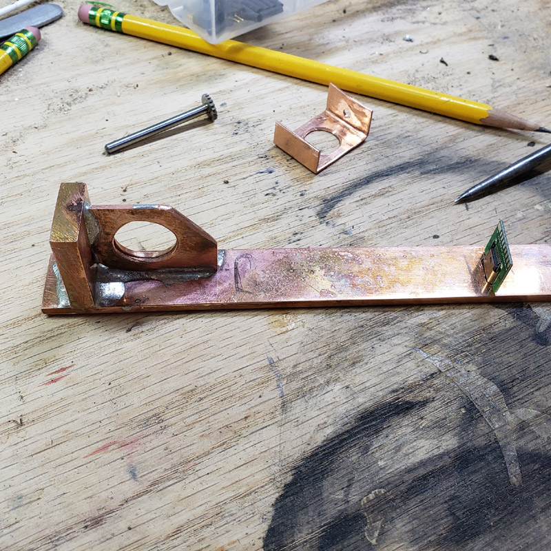
I needed a piece of copper plate with a driver sized hole bored in it. I started with this scrap. No idea what the stamped letter “P” was for. I started with a smallish drill bit and worked my way up to 5/8”
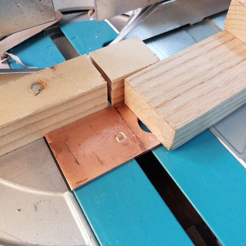
Then I used the miter saw and clamp to cut off what I need for this
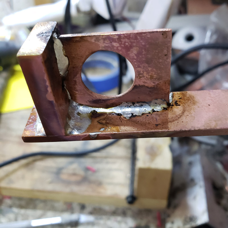
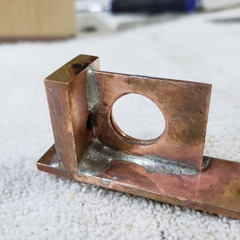
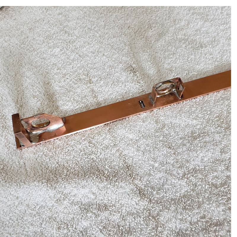
This new piece was clamped to the previously shown bar and silver soldered in place
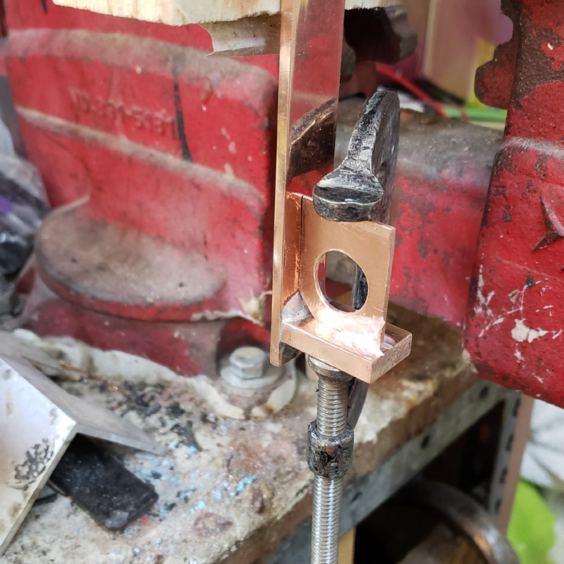
It looks a little messy. More so when the images presented are larger than life (depending on your monitor size.)
Metal work is not my forte.
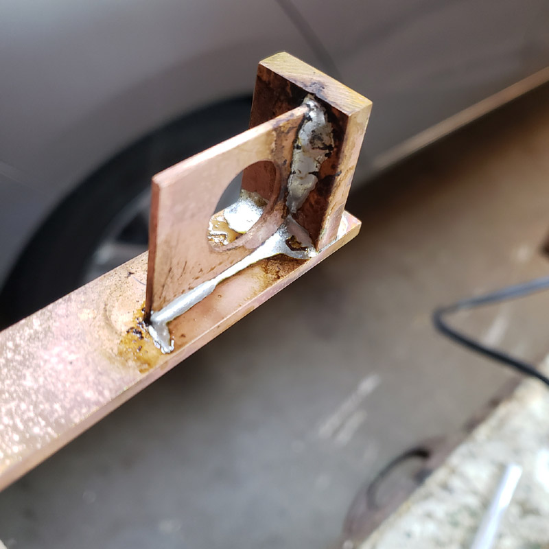
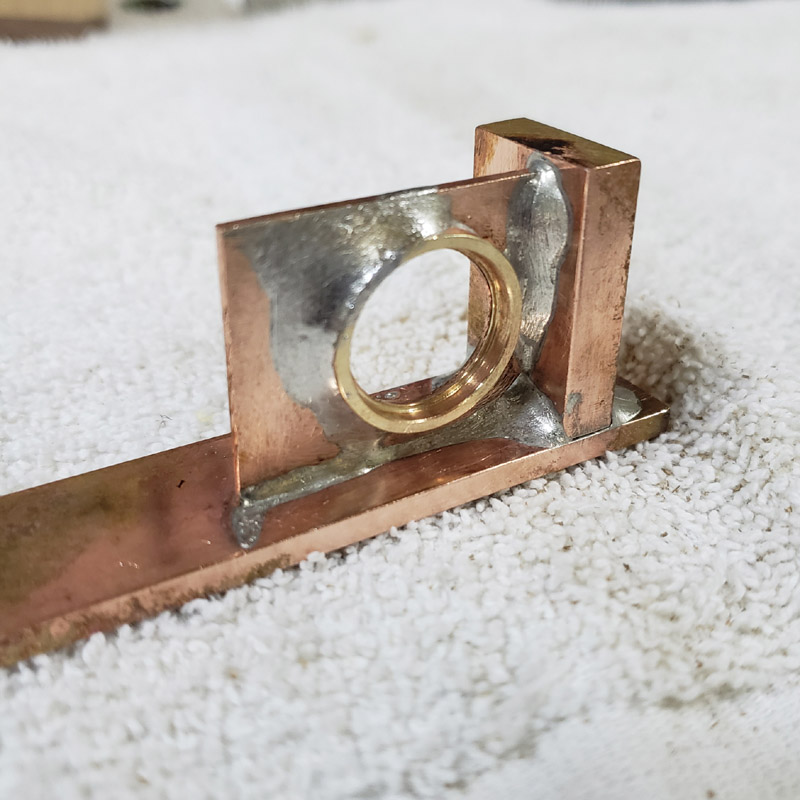
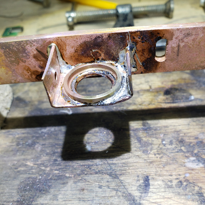
A 17mm to 20mm ring was silver soldered to one side of the plate with the large hole
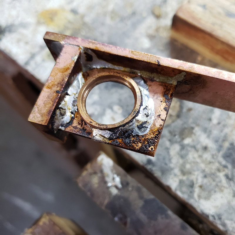
I cleaned up the flux residue
Thanks for having a look. More later; or another day.
That ought to be able to sink some heat!
P in this case stands for perfect. ![]()
I realized today that I have been remiss; I have neglected to state what I am trying to build for this project. ![]() All I’ve done is show an assortment of parts and a little bit of what I have done so far with cutting and soldering some copper bar stock.
All I’ve done is show an assortment of parts and a little bit of what I have done so far with cutting and soldering some copper bar stock.
So. I walk a lot. I walk in town for short errands. I also walk for exercise. Sometimes I walk in the evening when it is dark. Some of those walks are on roads without any street lighting. Some of those walks place me on or alongside a roadway. There may be vehicular traffic coming from either direction. When traffic is coming towards me I wave the light I carry about a little and am fairly confident they see me or see my light. I have thought that having a tail light would be nice. I even looked into using a bike tail-light.
This years contest build is an attempt to fulfill my desire. This light will have a typical forward white light beam with several levels. It will also have a rearward-facing red tail-light. ![]() With a stuttering blinky mode. And built-in USB recharging.
With a stuttering blinky mode. And built-in USB recharging.
I had mentioned a few sparse details way back. I have already altered some of that. This will have one Panasonic NCR 18650B cell, not two. It will have a 1 amp charger instead of a 2 amp as I have several on hand. Very likely a C-type USB port will be used, although since I am trying to use up parts that have been lying about for a while I might just use a micro. The front LEDs are from the miscellaneous, previously used parts box; a triple XP-L HI and the rear led an XP-E2 red. The red tail will receive one of the same spikey Ledil diffusers that I am using on the other, non-contest, project I have a topic on. Those Ledil’s were ordered from DigiKey; Ledil # C15419_ZORYA-MINI, in case anyone is interested.
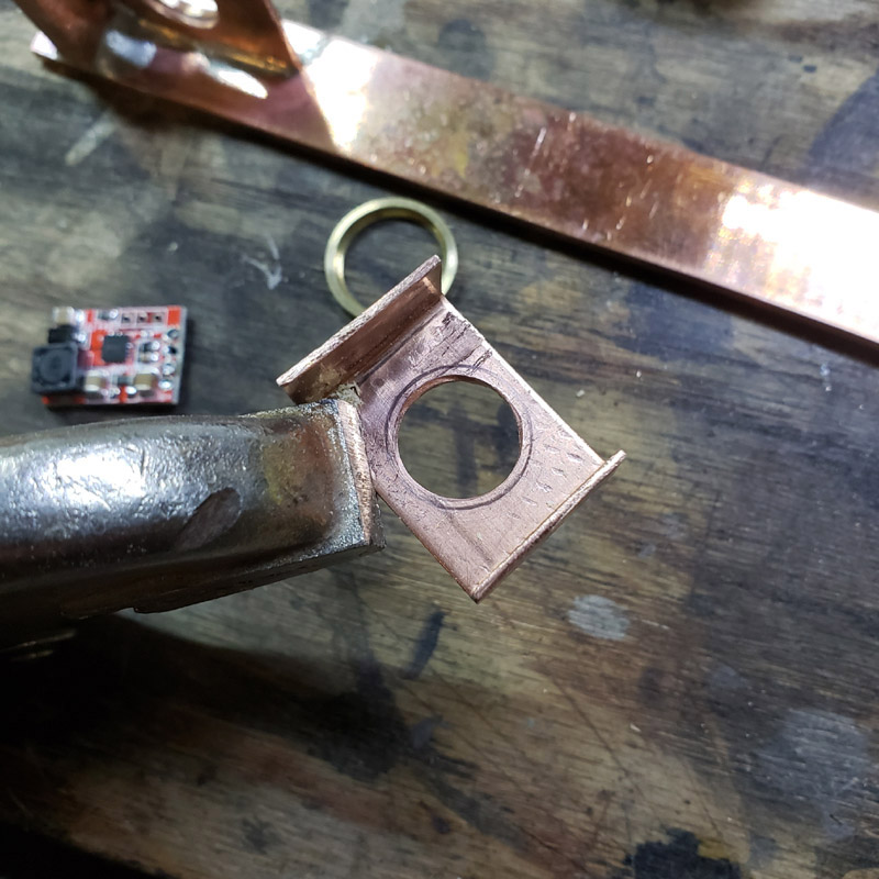
I did a wee bit of work on this tonight. I made a copper bracket that will be silver soldered to the previously shown copper bar stock. Just some cutting, bending and drilling.
It would be nice to have a sheet metal bending brake, but I make do with a vice, blocks of wood or metal and a hammer. …in process…
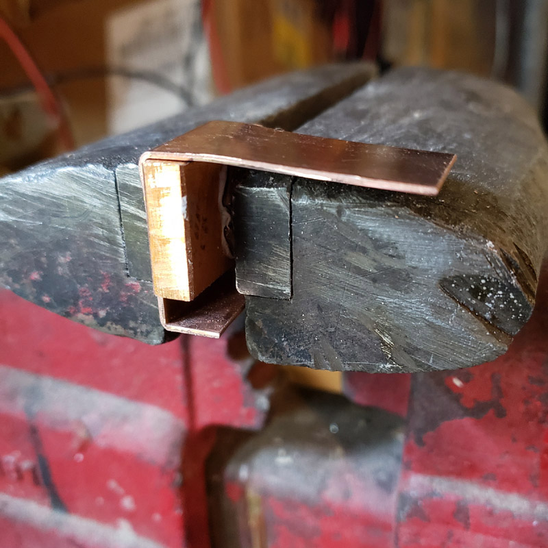
After bending and cutting and marking for a hole here it is… 18 gauge copper… The charger board to be used is shown.
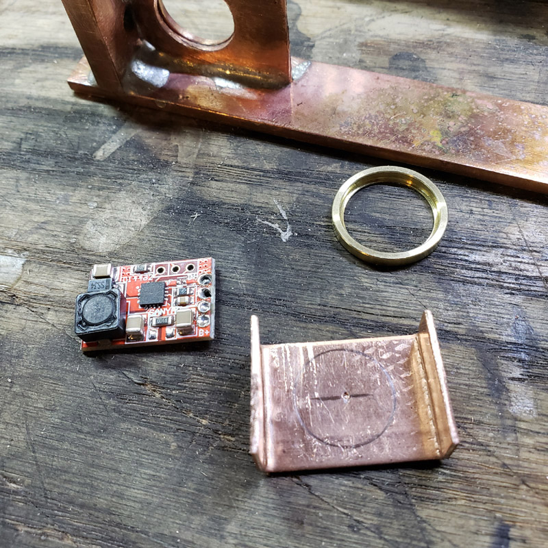
I drilled a 1/2” hole, in steps as before. This is for the rear light driver, a simple Nanjg101 (?). It doesn’t have as many smd’s as the front light Qlite so it doesn’t need as big a hole to clear the parts.
That will be silver soldered in due course. Before that though I need to make the tab where the mcpcb will mount as flat as possible for best heat conduction. Sanding…
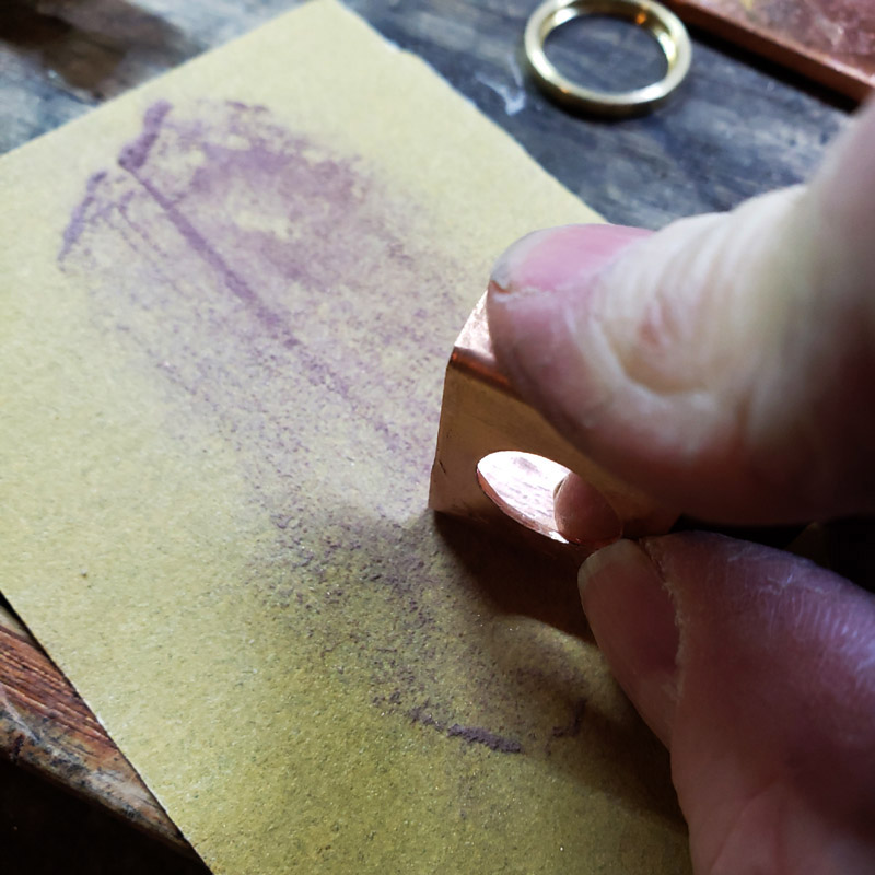
Not quite there…
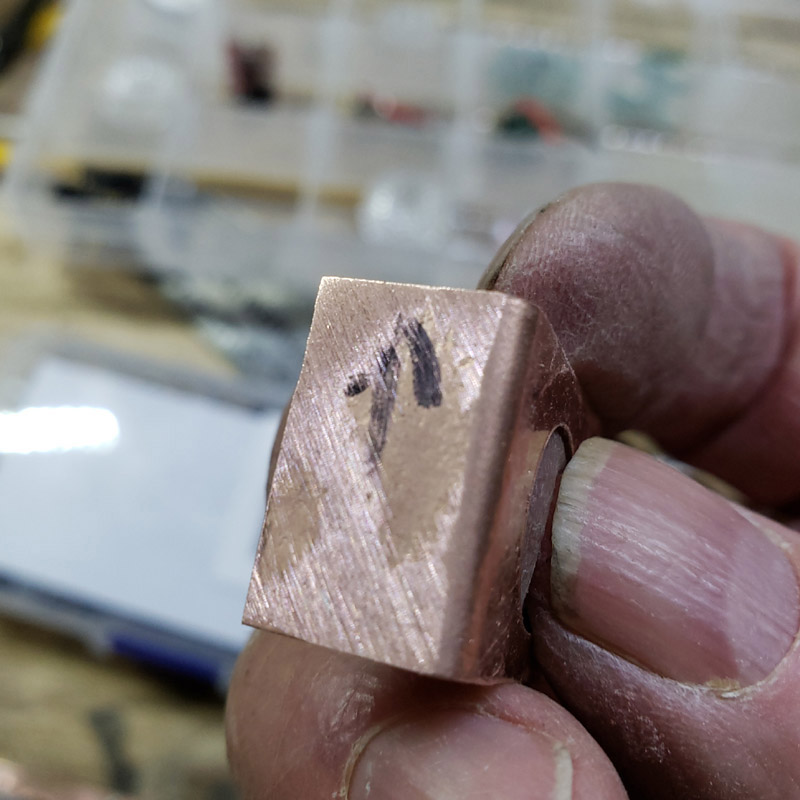
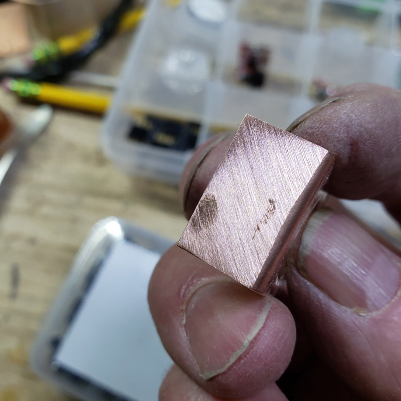
Just about perfect. Good enough for government work, as the saying goes. I did refine it but that image came out a little off focus so there is no proof to show at this time.
That’s all for today. Thanks for looking in.
Not sure what you used to drill the hole out Don but nice work. Holes like that are not easy to do.
As Dale has mentioned elsewhere. I’ll put my order in for one of these torches. ![]()
Thank you. I was more lucky than usual with that hole.
I did steps, starting with a 1/8”, then 17/64, 25/64 and 31/64”“; the odd fractions because those bits are not used as much as the 1/4, 3/8 and 1/2” bits and might be sharper. But still, most of the time a hole drilled in light gauge soft metal often ends up not round. Crazy.
![]()
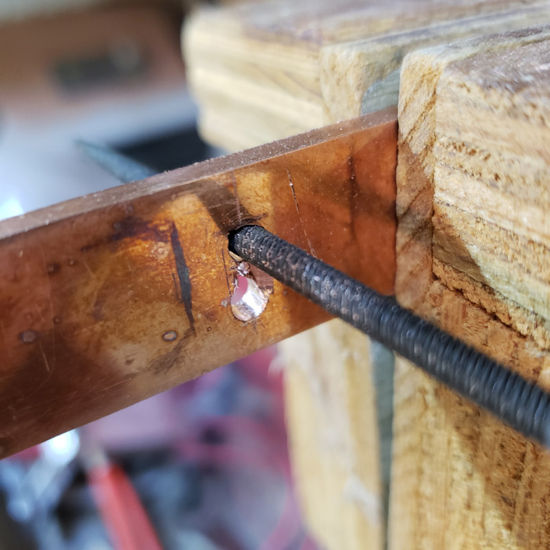
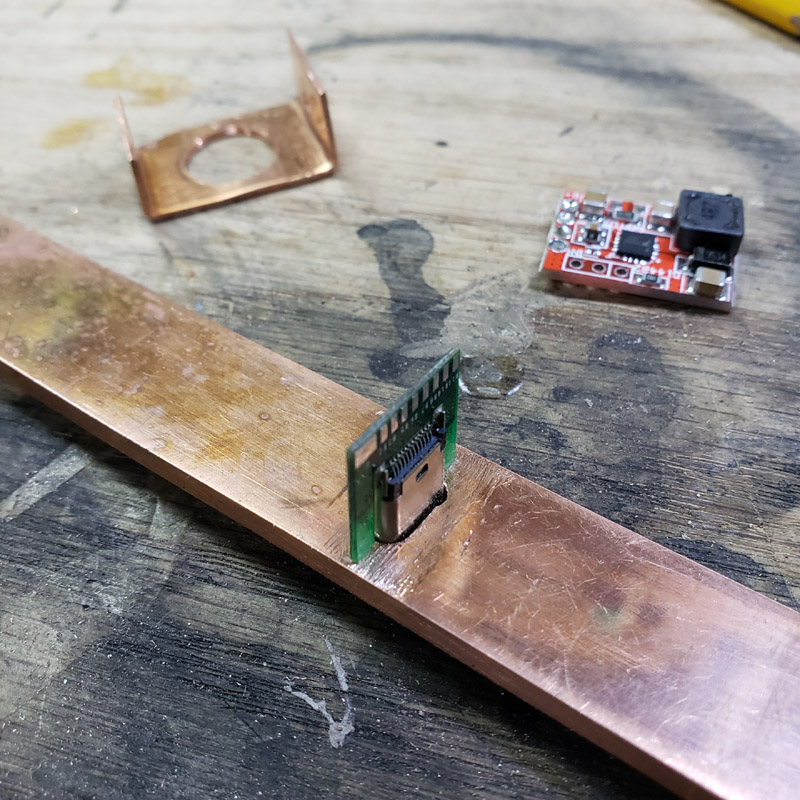
I’ve been kicking around a few ideas on how to implement the USB port and a couple of my ideas have problems. I decided the port will be placed in the bottom. It won’t be waterproof, but at least IF it rains the port is on the bottom and not likely to allow water to easily enter. Besides we don’t get a lot of rainy nights in NM and I try very hard to stay out of the rain. I do have other lights I can drop in a pail of water.
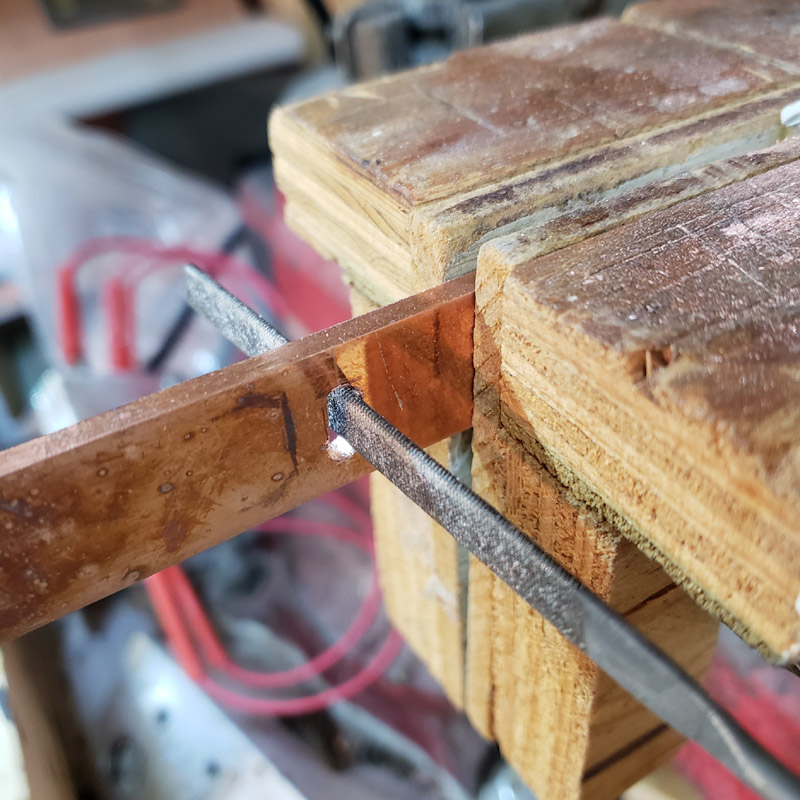
So, I needed to cut a slot in the bottom copper strap. I started with a pair of drilled holes and switched to small files.
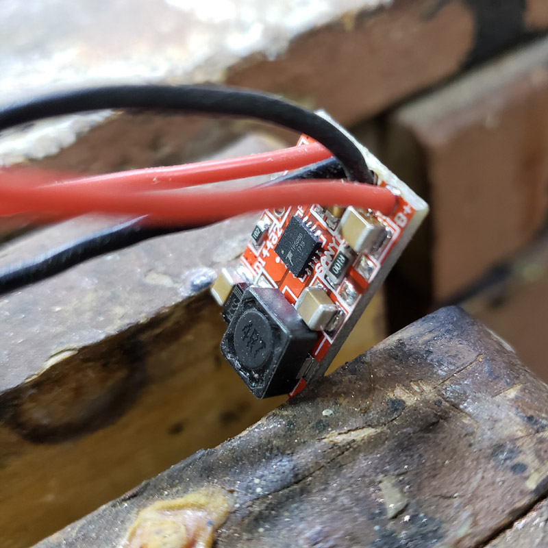
I thought it wise to test the operation of the previously used TP5000 charger board. It was a good thing I did as for some reason it would charge but the indicator led would not work. I tried 4 leds and had no luck. I tried the leds on another board and they lit. So this 1 amp board has been set aside. I have other TP5000 boards but they are slightly larger; still usable but a tighter fit.
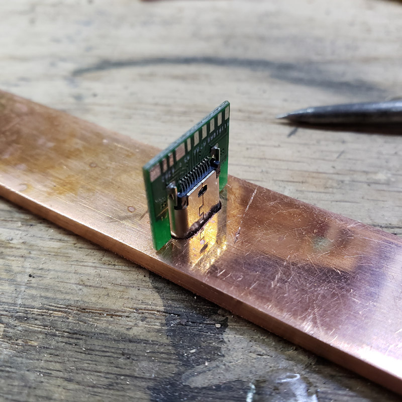
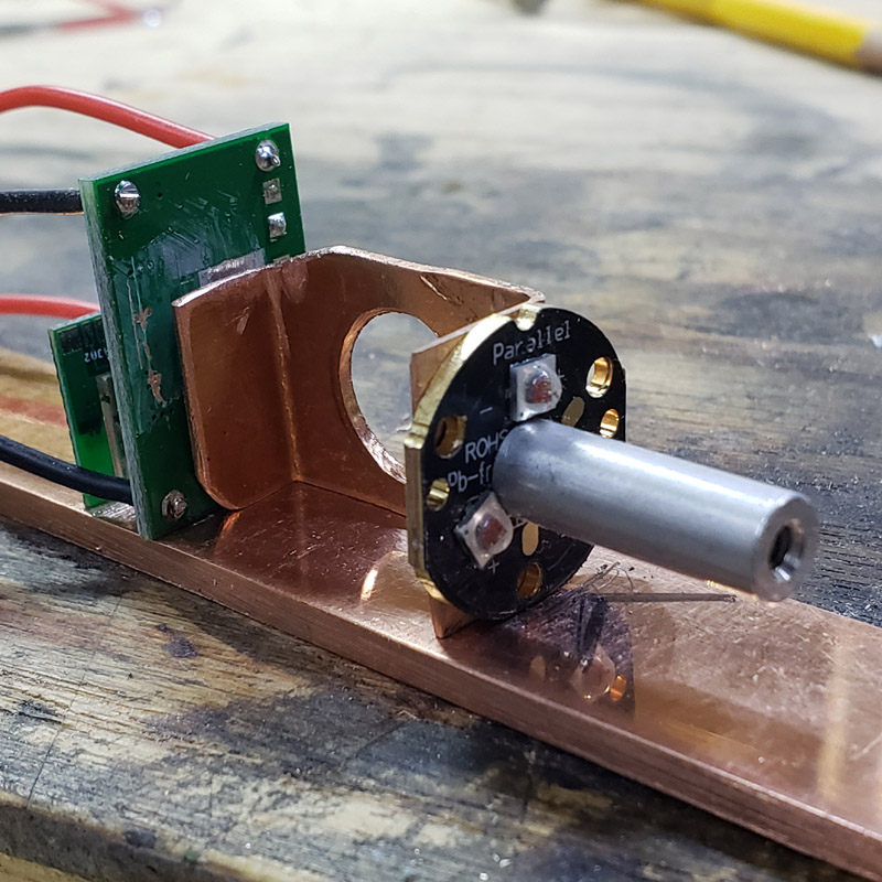
OK. Next are some pictures showing a mock up of the parts to be used and how they will be fitted… usb port, charger board, rear led. There is another change with the rear led. I have switched to using a triple XP-E2 red instead of the single. Reasons for the change will become apparent in a later installment.
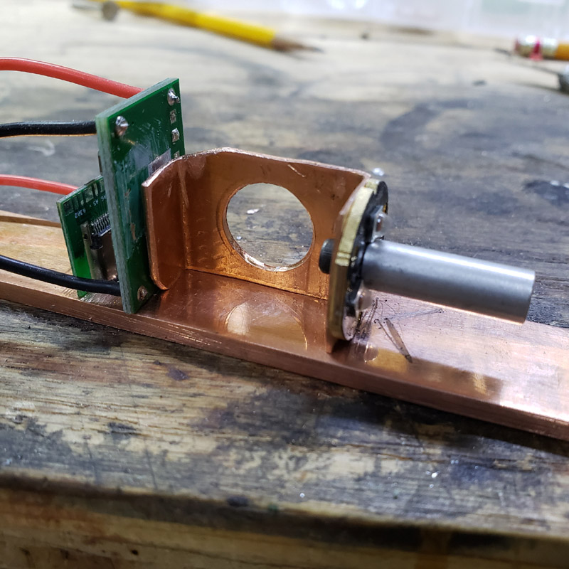
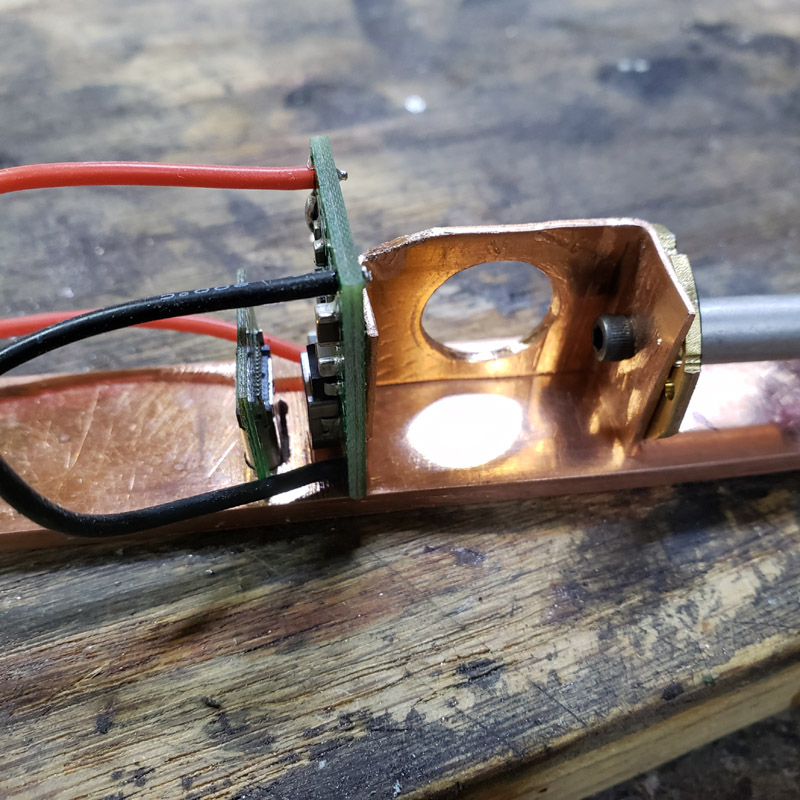
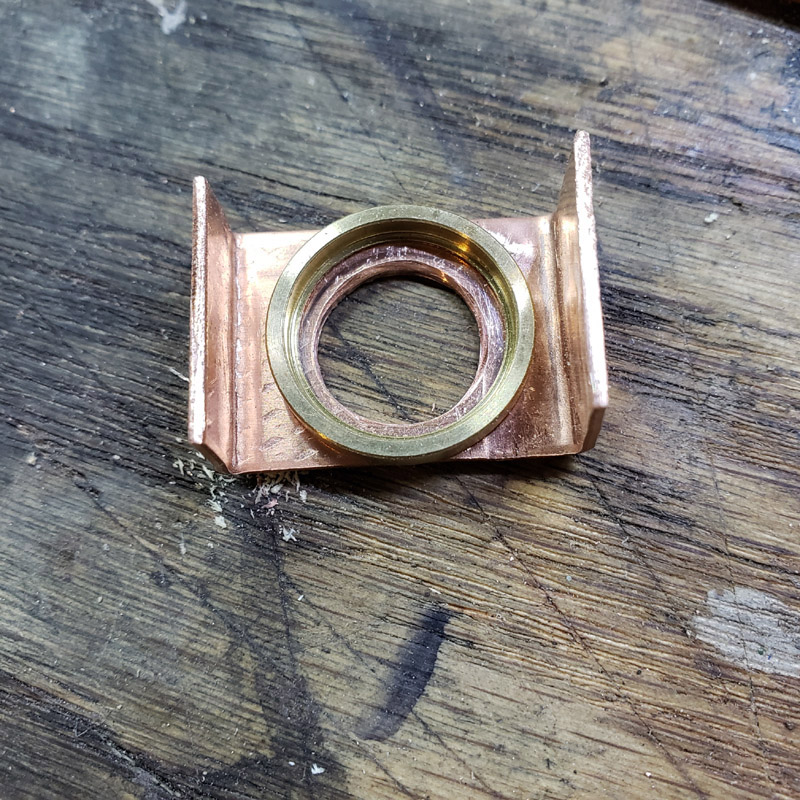
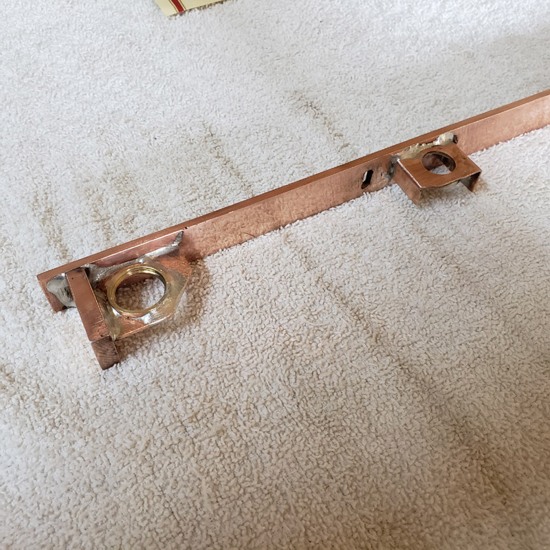
Next task was to silver solder the copper rear mount to the copper carrier. (I have taken to calling the assembly the carrier.) A spring clamp was used to hold the bracket while the soldering was performed.
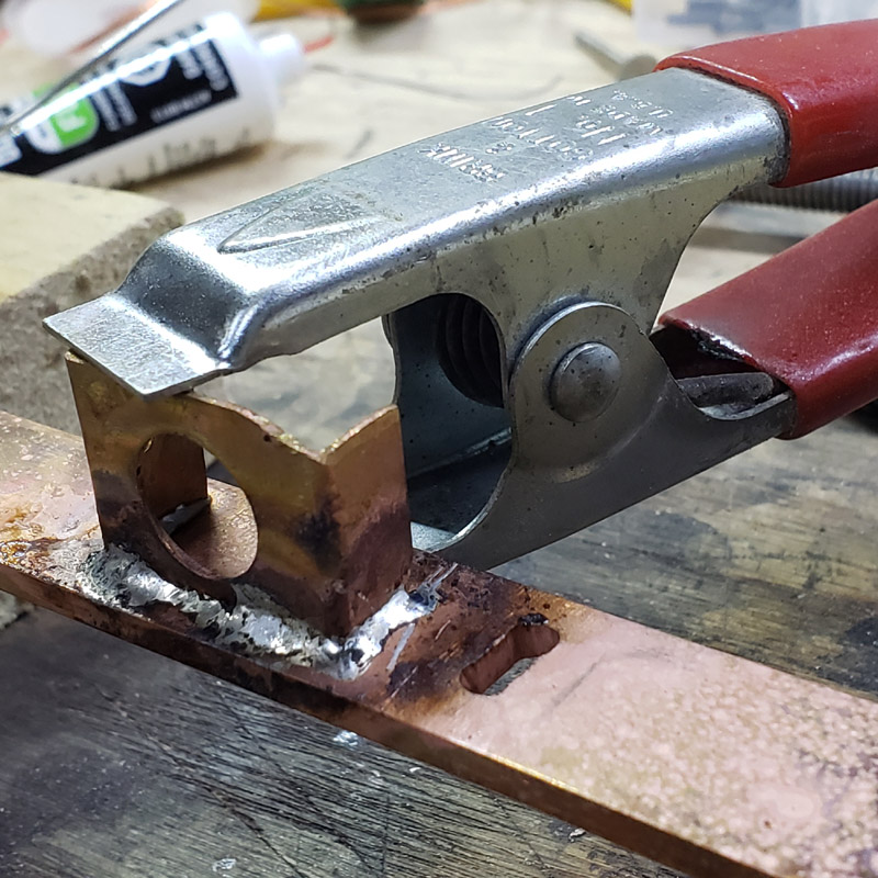
The ring that will mount the 17mm driver was then soldered in place.
I’ll take some more pictures after I clean the carrier up.
Looking good Don.
I’m intrigued to see how it all comes together MtnDon! You are very creative with how you’re using that copper.
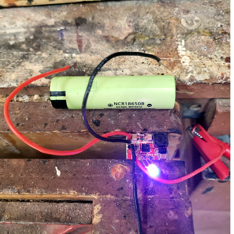
Some more work today. I located another 1 amp TP5000 board in a box where it did not belong. ![]() I tested it and it is fully functional, so it will be used. The NCR18650B cell should not be charged at more than 1.6 amps according to Panasonic so I didn’t really want to use a 2 amp charger and did not feel like changing the resistor on the 2 amp to alter the maximum charge rate. I can hardly see those little smd resistors let alone work with them. The cell is tabbed… tabs are almost invisible in the photo.
I tested it and it is fully functional, so it will be used. The NCR18650B cell should not be charged at more than 1.6 amps according to Panasonic so I didn’t really want to use a 2 amp charger and did not feel like changing the resistor on the 2 amp to alter the maximum charge rate. I can hardly see those little smd resistors let alone work with them. The cell is tabbed… tabs are almost invisible in the photo.
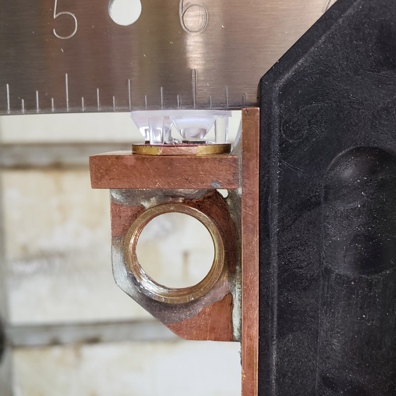
Below is a shot to illustrate the fitment of the MCPCB and Carclo optic. Everything is quite square and there is just a smidgen of clearance between the front of the optic and the leading edge of the carrier.
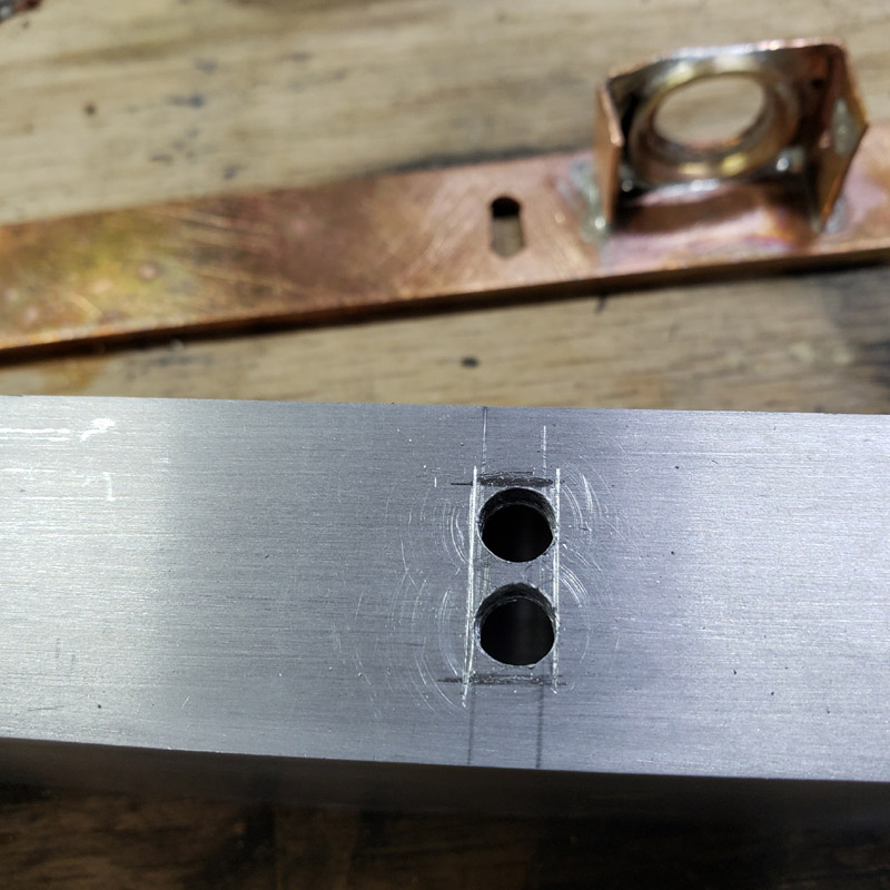
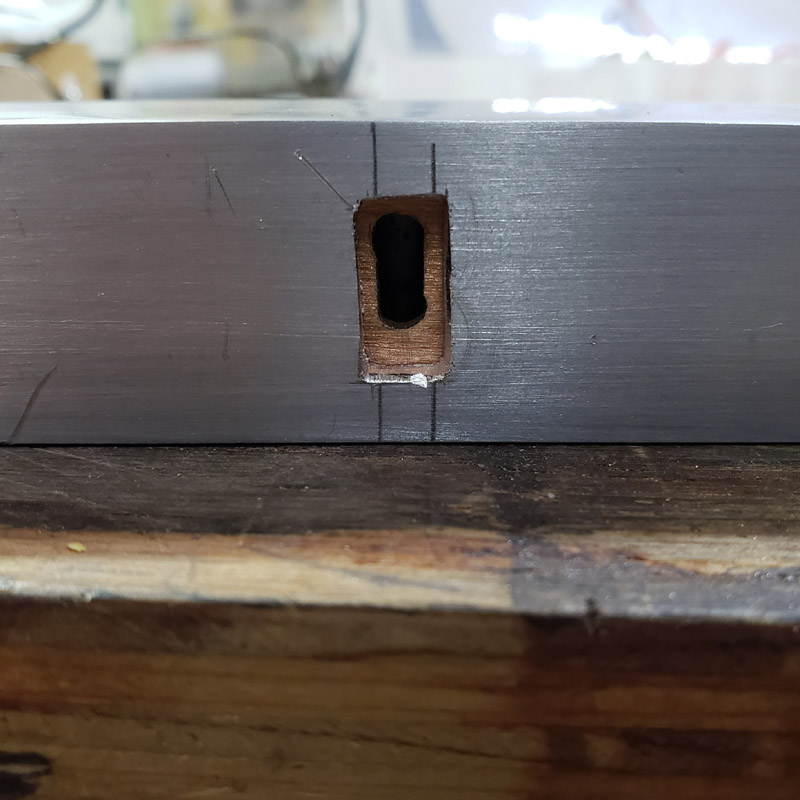
Time to make the port hole in the aluminum tube for the USB-C plug. We start with two 1/8” holes.
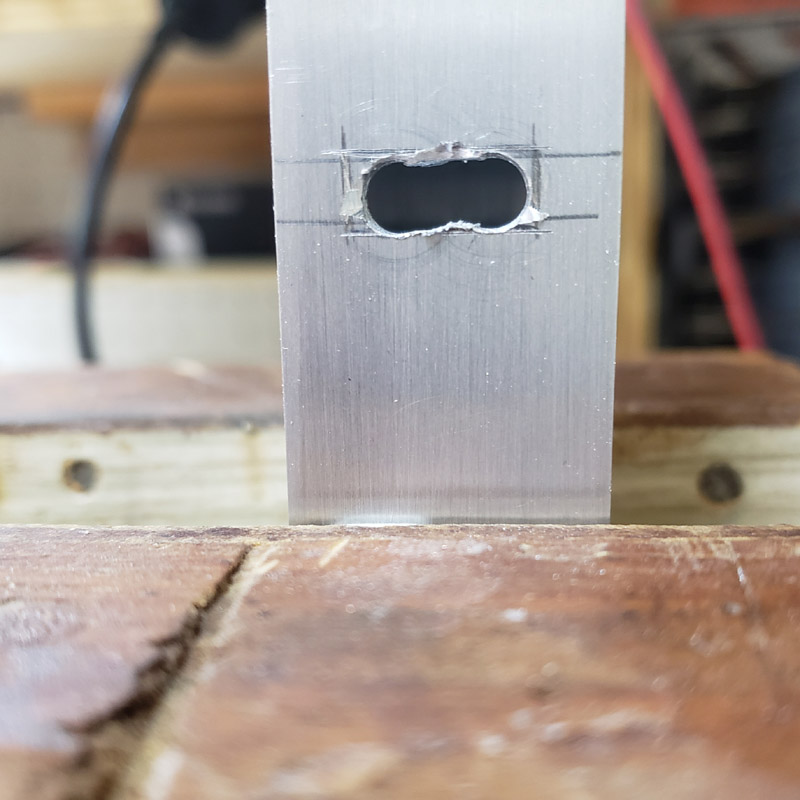
Then I used assorted small files to enlarge and make a rectangle. I sized the hole to clear the USB-C plug on a Samsung supplied cord. It seems a little bigger than some of the other cords I have.
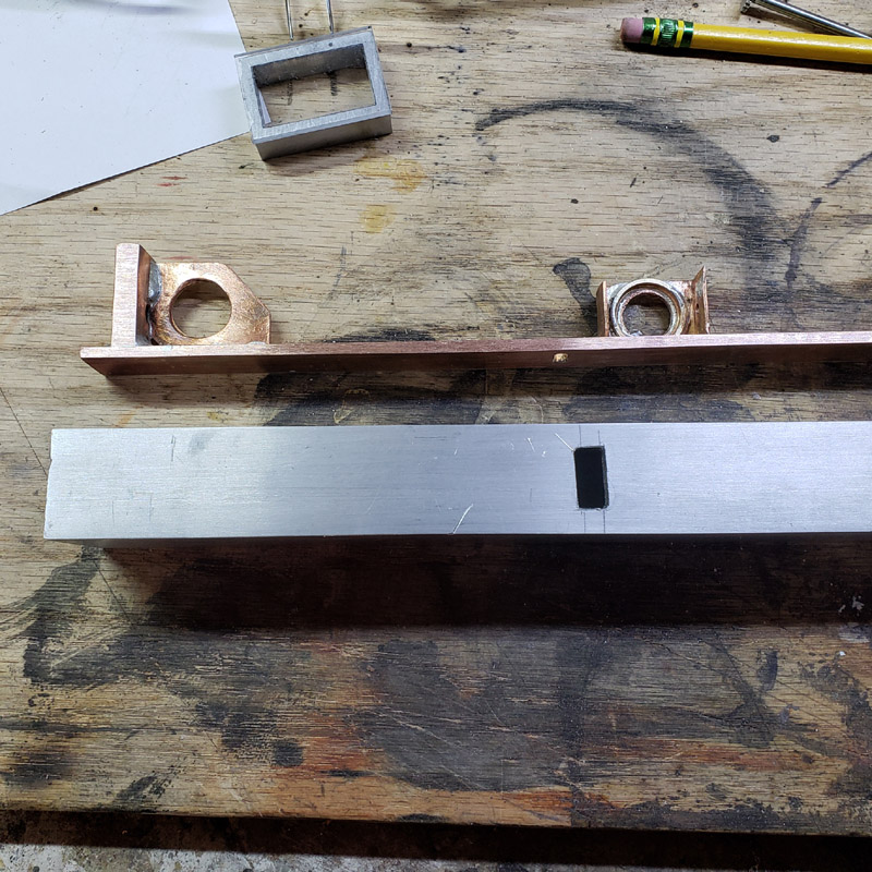
The carrier does slide into the aluminum tube.
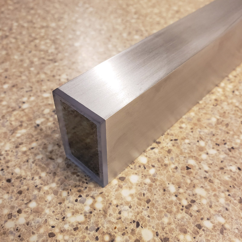
This shows the aluminum tube bottom (1” width) and the carrier.
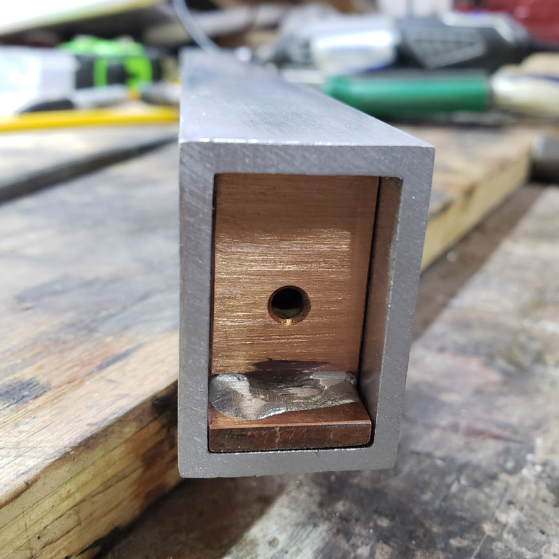
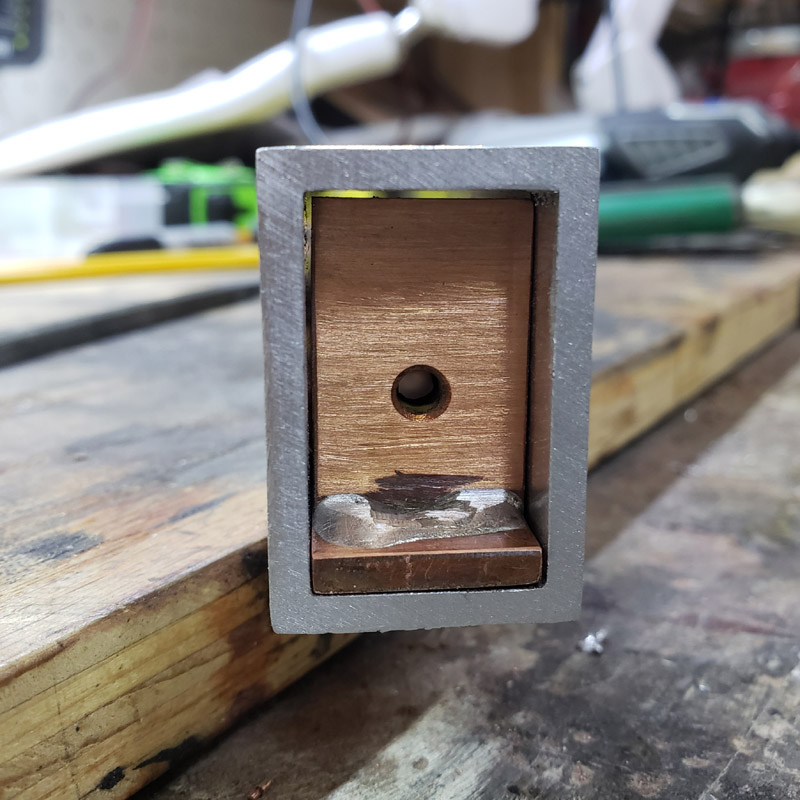
Next, three shots showing the carrier after I cleaned up the silver soldering residue. There should not be any further need for the messy silver soldering anymore.
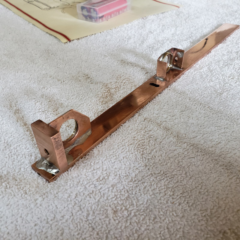
I should note that neither the carrier nor the aluminum tube housing will remain at their present lengths. They will be shortened. I have not been certain just how long it will be as I had not finalized the placement of all the components. Plus I have changed things while progressing.
![]()
I Love this one, keep the pictures coming ![]()
We agree again. ![]()
Love this! Nice work Don.
This is how I used to build stuff before I had access to a machine shop, and I really enjoyed it. Now I’m back to hand tools again.
Great work Don ![]() Looking forward to seeing it all come together.
Looking forward to seeing it all come together. ![]()
Your builds are impressive and classy ![]() This one is no exception!!!
This one is no exception!!!
Progress, I think…
I cut a piece of Lexan for a clear lens for the front end. The Carclo optic will be pressed up against the inside surface. Attaching the little rectangle of polycarbonate raised the question of “How?”.
I have tossed a few ideas around and settled on the direct approach; adhesive. However, that was not so direct as what I preferred would not work because of the material. I wanted to use a few drops of a crystal clear UV cured adhesive but belatedly remembered that polycarbonate is a UV absorber. Clear safety glasses, if made of polycarbonate and if they wrap around, offer protection against UV. I tried an experiment to see if it was so. I took a scrap of the aluminum tube and a piece of the lean, applied a few drops of adhesive and hit it with the light from my UV flashlight. Then I put it out in the sun for several hours. The Lexan seemed to be affixed when I first tried to pull it loose. But a good tap and it fell off. The very outside of the glue line interface between Lexan and aluminum had set hard. But that was just a thin film that was hard. The adhesive further into the joint was still wet; had not cured.
So, onto a variation of using adhesive. Cyanoacrylate. That worked fine. The potential downside is that the cyano is not waterproof. However, the joint survived an hour or so of wet sanding so I think I’m okay.
After the lens glue had set and the test piece I had also glued up at the same time proved to have a durable joint, I got out my wet/dry sandpapers and set about removing some of the fine scratches that came from the aluminum tubing being in the scrap boxes for some time. Tonight I used 120, 220, 320, 400 and 600 grit, using a flat board to work on.


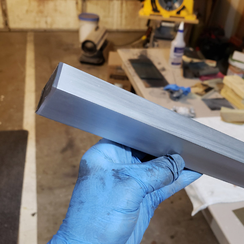
Here’s what I have at the end of my work tonight. The lexan lens and aluminum sanded smooth and with a matte finish.
I have not yet made up my mind how shiny I want to make the aluminum surface. Generally, I do not like glossy finishes. I like smooth matte to satin finishes. I do have sandpaper grits from 800, the next finest, up through1200, 1500, 2000 and 3000. Plus the surfaces are not going to be left as plain aluminum. I have some ideas to try to complement the metal.
Anyhow, there we are. I didn’t time myself but I was sanding, spraying water and sanding more for thousands of strokes. Probably over an hour.
Thanks for looking.
Very nice Don. Just glad its not me. ![]()