![]() I just wish I had more time. I have so many ideas and designs rolling around in my head… not to mention all of the partial builds and custom drivers awaiting tweaked firmware. Slowly chipping away one 2AM night at a time.
I just wish I had more time. I have so many ideas and designs rolling around in my head… not to mention all of the partial builds and custom drivers awaiting tweaked firmware. Slowly chipping away one 2AM night at a time.
While browsing for some ICs, I ran across these HM1160 chips which are bare-bones lithium battery life indicator ICs. They’re stupid simple and make it possible to create the battery monitoring tailcaps without a fancy teensy-tiny MCU and flashing firmware.
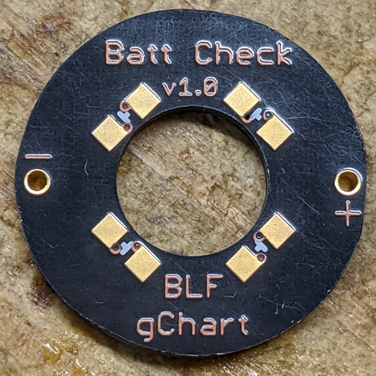
First off, the circuit boards using Oshpark’s new After Dark service. These are 15.8mm: small enough to fit a Tool AA (or SF14, etc) but should also fit Convoy S2/M1/C8/etc.
Here’s it in operation:

Public safety reminder… use protection. ![]()

I wanted to see if this chip could get away without a protection diode/FET. NOPE. I don’t want the voltage drop of a diode, so a V1.1 will be coming soon using a small FET for protection.
For the test shown above, I used a 680 Ohm resistor in series to mimic the bleeder resistor (which will have a marginal amount of voltage drop across it). With that in place, LEDs extinguished when falling below these approximate voltage levels:
- 3.85 V
- 3.63 V
- 3.46 V
- 2.98 V
Those aren’t where I’d necessarily pick them to be, be really it’s not too bad considering how convenient (and cheap!) these little HM1160 buggers are. To be continued… ![]()
How does current consumption compare to MCU based tail cap?
I haven’t measured yet, but it should be minimal. The HM1160 datasheet lists “Quiescent operating current” as 8 uA.
With how I’ve got the MCU’s programmed, they have a very low current consumption as well (using 32768 Hz clock with only periodic ADC activity). Datasheet says active power consumption using the 32768 Hz clock is 10 uA for the clock itself (2.6 uA in idle). I think I’ve only got the ADC turning on for a moment of every hour, so that shouldn’t draw much current.
Good. ![]() 4 years on 10440. Does it include LED current? I guess no?
4 years on 10440. Does it include LED current? I guess no?
Nope. That is dependent on what you use for the resistor. In the one I just put together for my Tool AA Ti, I used a 20,000 Ohm resistor. I haven’t measured actual current draw yet, but it should be roughly 0.08 mA (80 uA) on a full battery. Calculation goes a bit like this:
Battery voltage: 4.2 V
LED forward voltage: 2.6 V
Resistor used: 20,000 Ohm
(4.2 - 2.6) / 20000 = 0.00008 A = 0.08 mA = 80 uA
Battery drain (worst case scenario, current will actual drop as the battery voltage drops):
1000 mAh battery ÷ 24 hours/day ÷ 30 days/month ÷ 0.08 mA = 17 months standby time
It’s bright enough to be mildly visible in a decently lit indoor room. Illumination not visible outside during daylight. Relatively bright in a dark room.
Thats interesting gchart. Very simple, just wish it had voltage adjustment.
Couldn’t you add a small resistor in series to vcc to create a slight v-drop in the 10 to 20 mv range to lower the led voltage cut off points.
I haven’t a clue how you could increase them.
.
Are these pcb’s shared on Oshpark?
A series resistor can/does create a slight voltage drop, but probably not a enough to make it worthwhile to chase. Honestly, I think it’s just convenient & cheap enough to not worry about the small details. They’re directionally correct and informative.
Oshpark links:
- Version 1.0, lacks reverse polarity protection but works fine otherwise (this is what is in my Tool AA)
- Version 1.1, adds a small PFET for reverse polarity protection. (waiting these to arrive, should be here in a week or so)
- Version 1.2, opened up the center hole a bit for better fitment (not yet tested)
I did notice that while installing v1.0 in my Tool that the center hole is slightly narrower than expected and I had to spend a minute lightly sanding the switch to allow the PCB to slide on it. The dimension I used was the same as with other boards, so perhaps it’s just board-to-board variation. Or perhaps it’s a process difference between the regular service and the After Dark service. If my v1.1 arrive with slightly narrow cutouts, I’ll likely open that hole up and call it v1.2.
Thanks for the links gchart. I got too many projects on going right now, but I’ll give it a try in a week or so. ![]()
Sending you a PM.
Sounds good. FYI, I just went ahead and made a v1.2 with a slightly larger center hole. That way if anybody cares to order some, that’s already taken care of just in case.
looks cool
where to get the parts gchart?
The HM1160 came from AliExpress. The capacitors, resistors, and LEDs I already had on hand from past projects.
thanks gchart ![]()
is it possible to get the rest of the conponants on aliexpress
resistors and leds and caps etc, i wouldnt mind makeing a few of these
you think they would also work on convoy c8 and s2s
thanks
Can you give the BOM for this v1.2?
Thanks gchart.
BOM:
- HM1160 - I’ve only found it on AliExpress, can sometimes also find it by it’s chip label “60AA”
- PFET, size SC-70 / SOT-323 (such as BSS209PWH6327XTSA1)
- 1uF 0603 or 0805 capacitor
- A resistor of your choice (I generally use 10k - 30k Ohm) in 0603 or 0805 (for setting the brightness)
- 4x LEDs of your choice, 0805
Don’t forget a bleeder for your driver, something around 680-840 Ohm
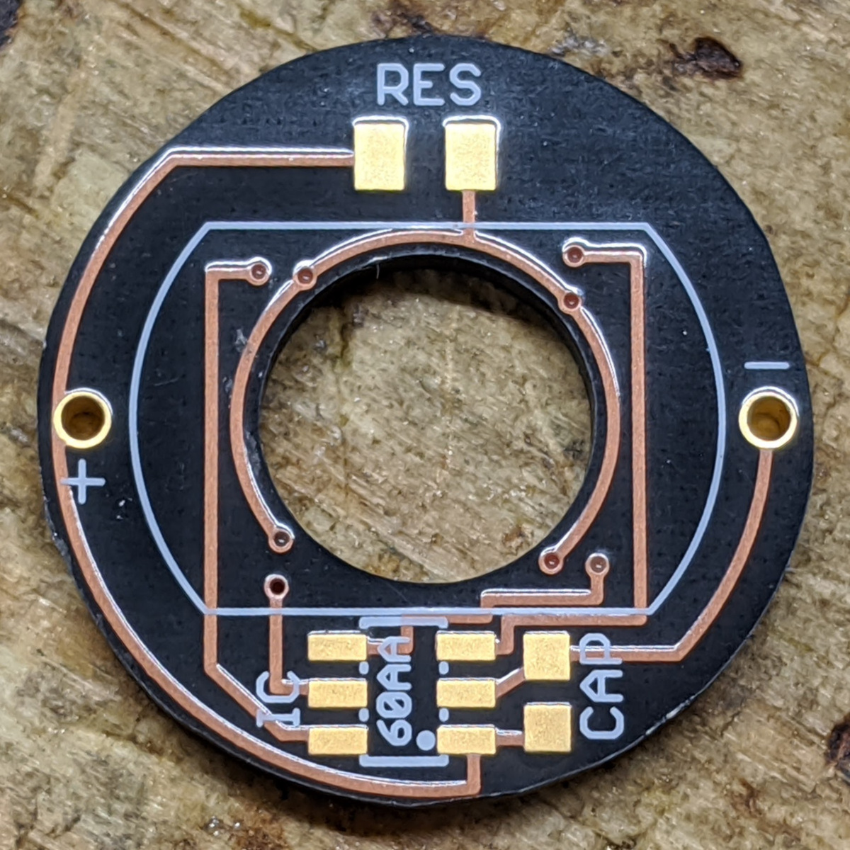
Oh yeah… If this is going in something bigger than a Tool (a Convoy S2 / C8 perhaps), you could use this single sided board to make things easier. It’s squared off because I’m cheap ![]() (the square inches you pay are based on the smallest rectangle that can fit around your design). I have dinner of these on hand but haven’t assembled them yet. I expect them to work fine as they’re electrically the same, i just have had a moment to put one together.
(the square inches you pay are based on the smallest rectangle that can fit around your design). I have dinner of these on hand but haven’t assembled them yet. I expect them to work fine as they’re electrically the same, i just have had a moment to put one together.
Additional information regarding the HM1160 chip.
I’ve been curious about the exact cutoff voltages. And sometimes I noticed a slight difference using my power supply vs a battery. So I managed to dig up an extended datasheet in Chinese, which I ran through Google Translate. From it, I was able to pull the official cutoff specifications. They are as follows:
| Volt Range | VD1 | VD2 | VD3 | VD4 |
| 3.87-4.2 | Bright | Bright | Bright | Bright |
| 3.7-3.87 | Bright | Bright | Bright | Extinguish |
| 3.55-3.7 | Bright | Bright | Extinguish | Extinguish |
| 3.4-3.55 | Bright | Extinguish | Extinguish | Extinguish |
| 3.4 or less | Extinguish | Extinguish | Extinguish | Extinguish |
So… the “official” cutoff levels are: 3.87v, 3.70v, 3.55v, and 3.40v. You might be thinking, as I did, “hey, 3.40v seems really high to be the lowest cutoff! I’ve been taught that lithium-ion batteries are good down 2.8v.” And that’s not wrong. But it’s too easy to think of remaining capacity as being linear with cell voltage. But that’s not the case. HKJ has a great write up about this. Here’s an image from that article:
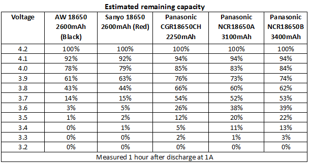
I used his battery comparison tables and came up with similar figures for some of my most used batteries:
table(table#posts).
||Shockli 1000mAh 14500|Samsung 35E|Samsung 30Q|Average|
|3.87 v|76|68|69|71|
|3.70 v|58|48|45|50|
|3.55 v|24|29|35|29|
|3.40 v|6|16|21|14|
Armed with this knowledge, you could say about the HM1160:
- 4 LEDs on: 100% - 71% remaining
- 3 LEDs on: 71% - 50% remaining
- 2 LEDs on: 50% - 29% remaining
- 1 LED on: 29% - 14% remaining
- No LEDs on: under 14% remaining
Doesn’t sound so bad now, huh?
Circling back around… some of these cutoff values are different from what I initially proposed using my basic variable voltage source. I think the difference lies in that the HM1160 behaves slightly differently when a consistently-connected source is dropping in voltage vs when a source is first applied. That is, when crossing the 3.40v threshold from above by ramping the voltage supply down, the last LED wouldn’t extinguish until around 3.2 - 3.3v. But if I disconnected the tailcap, set the supply to just under 3.4v and reconnected the tailcap, the LEDs wouldn’t light up. I imagine there must be a bit of a buffer zone to keep LEDs for flopping back and forth when the measured voltage is right around a cutoff.
There ya have it… the HM1160.
Wow nice finding gchart! Thank you for providing this info. I think I’m gonna stick with v1.0 first, it’s difficult to find the PFET here…
Regarding to the small opening for switch, can I enlarge the center hole on the board or should I sanding the switch?
I ordered two batches of v1.0 and one was too tight and one for just fine. Manufacturing tolerances I guess. I was able to carefully drill the boards out just fine. 7mm I think, you’d want to measure.
Nice practical reference charts on practical battery capacity - I guess gChart stand for “Great Charts”.
I was a big fan of how your HM1160 tailcap performed on the video. But it’s understandable, there’s a difference in how the circuit behaves using a stepped down DC power supply versus actual batteries. I guess the ideal chip was too good to be true ![]()
Personally I think the 3&4 LED cut-offs ranges are fine but the 1&2 cut-off ranges are a little too early. The earlier video showing cut-off/extinguishing of all 4- LEDs at 2.9-3V was ideal because it simulates Protected Battery cut-offs. Cutting-off at 3.4V even if there’s only 6-21% remaining is a little early (1 LED was ideal.)
Just a thought - would it be possible to slap a capacitor into the circuit somewhere to help get the LED excited enough to light up on battery power, thus getting closer to it’s performance as on the video using a DC PS?