The old pencil on capacitor trick, nice ![]()
Good deduction, perseverance testing and showing results of the NMM times too ![]()
Looks like a big bag of resistors from FT, always come in handy.
Nice. NMM is a deal breaker.
Well… Confession time. My DQG Slim AA has NMM sometimes. It’s pretty unpredictable on mine. But I put up with it because it’s so otherwise nearly perfect.
Thanks all for the kind words. I should clarify that I’m well aware that I didn’t invent the pencil trick, but I’ve never seen it done on a Ti3 V2 so I thought it was worth posting about.
Hopefully going to do a few other things to this light besides fixing the NMM…we will see how it goes.
I have now tested several resistors soldered over the capacitor that I suspect is responsible for the NMM. By the end, I got better at the soldering. These things are really small.


After trying a couple of resistors and testing using the test wires, I got NMM length of ~6 seconds with a 100 kohm resistor. Great! So I reassembled the light. But the NMM was lasting longer when assembled, ~17 seconds. I’m still not sure if this is a real difference, or how to explain it. At some point, I realized that I could assemble the driver/pill/MCPCB and that the wires were long enough to still access the driver, so I didn’t have to use the test wires like I showed in the first post.

So I tried more resistors, trying to tune the NMM to a desirable length of ~5 seconds. Unfortunately, it seemed like I was getting diminishing returns, and the light when assembled never went below NMM of ~11 seconds. The NMMs with a resistor on the capacitor were generally very repeatable, and I tested each resistor several times. Here is a table of the results.

At this point, I’ve started working with my brother, who is an expert in electronics and such. He made some assumptions about the circuit, and then did some circuit simulations, but couldn’t replicate the results that I was getting. One of the oddest parts is the capacitor discharge time, which can be easily calculated. Even if the only parallel resistance is one of the resistors that I tested, and the capacitance is the highest possible for 0603 package (which I believe is 47 uF), the capacitor is generally discharged long before the NMMs that I observed. This is true if the capacitor is charged to 1.5V battery voltage, or by the boost converter to ~3V.
Maybe some of the assumptions about this circuit aren’t true though. So I bought my brother a new Thrunite Ti3 V2 from Amazon to look at (since he lives on the other side of the country). He found that the NMM only lasts ~10 seconds though, unlike my example. However, it goes into strobe seemingly randomly. The mode sequence is supposed to be L-M-H-L-M-H-S, but his light often goes into strobe straight from low or medium.
That’s all for now. We are going to try to learn more and figure out what can be done.
Interesting mod The Whispering. You are certainly doing a lot of experimenting to get rid of an old Chinese favourite. ![]()
Welcome ” The Whispering ” to the fun. ![]()
You certainly are experienced at modding lights, nice explanations of your operations. ![]()
Thanks to you both. I wouldn’t say I’m all that experienced…especially compared to some of the amazing projects done by BLF members. I’ve enjoyed reading through the other threads in this contest, including both of yours. Just trying to learn and have fun with this ![]()
I hope you can figure this out The Whispering. So does it seem the pencil trick had the best results so far? My Astrolux A01 has similar behavior, but much longer off time. I give it a pass though due to it’s Nichia 219B.
Ok, the next thing I did was solder some wires on the capacitor so that I could measure the voltage across the capacitor when the light is on. I found that it varied from about 2.4-2.7V depending on the mode. The capacitor is charged by the boost converter, so low mode gives the lowest voltage and high mode give the highest voltage.

After some discussions with my brother, I made some rough assumptions that the minimum voltage to power the MCU is ~0.6V, and that it uses on the order of uA. At this point we don’t know the capacitance of this capacitor either, so I made the table below to show the expected length of NMM for various capacitors and parallel resistance (the resistor which I soldered onto the capacitor). 50 uF is about the max capacitance for a 1608 capacitor, and 1E6 kohm represents the unmodified flashlight where only a few uA are drawn by the MCU. I defined NMM length as the time for the capacitor to discharge from 2.4V to 0.6V. The equation is Vc=Vo*e^(-t/RC), where Vc is the capacitor voltage at time, t, Vo is the initial voltage, R is resistance, and C is the capacitance.

The problem is that this doesn’t match any of the behavior that I observed, namely that I was getting NMM lengths of >10s even with the 1 kohm resistor. So I concluded that I’ve been working with the wrong capacitor, and started trying the others.
This one turned out to be the right one. I drew a pencil line first, and then cleaned it off and soldered on some wires to check the voltage, which was also about 2.4-2.7V. Then soldered on a 1 Mohm resistor (the highest that I have), and the NMM was ~3s.
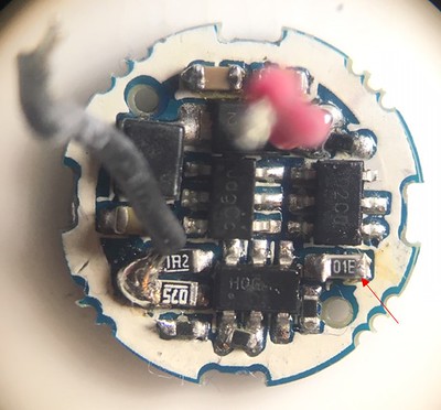
Based on the assumptions used to generate the NMM table, the capacitance of this capacitor is calculated to be ~2 uF.
I was happy with these results, so I decided to reassemble the light.
Good to see it working. Your persistence is impressive. ![]()
Reassembly:
I first had to do something about the inductor that I damaged, so I put on a little bit of this MG Chemicals 832 HD potting compound with a toothpick.

Then I used my reflow station to install a Nichia 219b 3500k R9080 LED, and reassembled the driver, pill, and MCPCB.
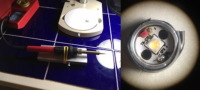
Added some commemorative laser marking for the 7th Old Lumens contest, and took a quick beam shot next to my Ti3 titanium with 219b 4500k R9080 (which has the new shorter and fatter V2 body and came with only 10s NMM and works flawlessly). Both LEDs look great in real life.

Here is a close-up of the laser marking. Mine didn’t come out quite as sharp as that done by Thrunite.

Edit 2/28/20:
To put some data to it and check the consistency of the NMM length, I did 10 tests each of two different off times. Unlike the original light, which had seemingly random NMM times tested up to 10 min (shown in the first post), after the resistor mod I found the behavior to be repeatable.
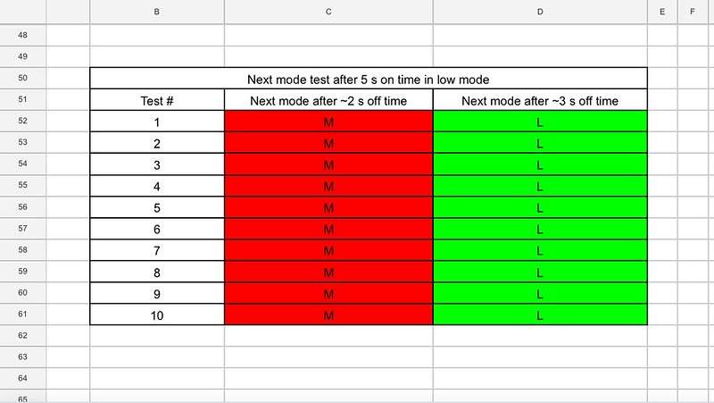
I consider this light to be complete. I’m going to use it for a little while to make sure that there are no issues and then post a giveaway for it. My brother has also reverse engineered the circuit now and I will post that information soon.
It’s been an honor to participate in this contest. Congratulations to all the other participants on their excellent builds and modifications.
Congrats on finishing ![]() The laser treatment is a nice touch
The laser treatment is a nice touch ![]()
![]()
![]()
Good presentation ![]()
That really helps us to understand the detail operations going on inside a driver. ![]()
Great Finish with the laser ![]()
Nice work The Whispering. Nothing like a custom light to suit your own needs. ![]()
Great work and persistence ![]()
Surely a keeper after all this ![]()
Wait, what, you have a laser that does that? Impressive The Whispering!
Thanks all. I’m really grateful to those that organized this contest and to BLF in general. I learned a lot doing this project, and that is by far the most valuable takeaway. Stay tuned as I’ll be giving away this light as well as a few kits from the leftover resistors to raise awareness for next year’s contest and encourage more projects and new participants (will take some time to sort through the resistors).
P.S. I don’t own a laser engraver, just had the opportunity to use one.
Here is my bro’s report. This is all his work and I didn’t contribute anything. Note that his example of the light had consistent NMM of 10 s, unlike mine.
1. Reverse engineer the design and capture schematics.
Here is a description of the main circuit components/functions:
- B1: AAA battery
- D2: The LED
- U2: Microcontroller (Probably ATTiny4 or PIC10F200)
- U1, C1, L1, D1, C2, C3: Boost converter to drive forward voltage of LED
- FB node of U1: feedback pin - constant voltage reference that provides control loop input for regulating current through D2. I_LED =
- V_FB/R_Sense, where R_Sense is the parallel combination of all enabled sense resistors R1, R2, R3.
- R3: LOW mode resistor (always on)
- Q1A/R1, and Q1B/R2: FET which enables the corresponding sense resistor; enabled by MCU to change brightness
- R4/R5: Pull-down resistor on gate of FET to prevent undefined state
- C4: The decoupling capacitor for the MCU. This is what allows the MCU to stay alive during the NMM time. In general a decoupling capacitor provides a low-inductance voltage supply to satisfy the load’s (IC) transient current spike requirements.
- D3: prevents discharge of decoupling capacitor through LED. This is what allows the MCU to stay alive during the NMM time.
- Methods
R1 and R2 values were read off the resistor and confirmed to be within range using multimeter. Since the values were so low, a 4-wire resistance measurement out of circuit would have been required, but was not done since the value was printed on the resistor.
R3 was measured in-circuit
C4 was measured in-circuit

2. Take key measurements
The circuit was instrumented for measurements. I soldered 18AWG stranded silicone wire to the board for low resistance connections, since we are dealing with very low sense resistors, and a very low current in LOW mode. The LED anode wire had to be lengthened to fit the current clamp probe. For the battery power input, I scratched off the soldermask on the back side and soldered the wires there because I didn’t want to get solder on the battery contacts (and I wanted to preserve the ENIG finish) in case I wanted to reassemble this flashlight. These wires were connected to a 1.5V DC bench top supply.

Results:

Discussion:
- High mode measured current implies a combined parallel sense resistance of 0.13 ohms, or an R2 value of 0.15 ohms. It is very plausible that the extra 0.15-0.075 = 0.075 ohms comes from the on-state resistance of the pass transistor, Q1B.
- Low mode current is very difficult to measure. 0.68mA is very close to expected.
3. Determine voltage threshold for moving to next state
- Initially this was attempted by probing the voltage decay on the microcontroller power rail using an oscilloscope. However, the 10Mohm input impedance of the oscilloscope seemed to cause a fast decay of the power rail. After about 6s the capacitor has fully discharged.

- Next a bench top multimeter with a 10Gohm input impedance was used. Since this could not capture the waveform, I set a 10s timer (NMM time determined in previous experiments and stated in the user manual) and read the voltage at this time. The voltage was about 300mV. Image is for reference only, not the actual voltage that was seen at 10s.

- Now, taking into account the 1uF capacitor, a 300mV threshold, and a 10s NMM time, we can approximate the load presented by the microcontroller. It turns out to be about 4.5Mohm.

- Next, we can use a resistor to model the microcontroller load in simulation. Our results confirm that ~300mV is reached at 10s.

- Now we can add a second resistor and adjust until we achieve the 300mV threshold at the desired NMM time. In these tests we achieve a 3s NMM time by adding a 1.8Mohm resistive load.

4. Limitations to this study
- The sense resistors (1.2 ohms and 0.075 ohms) are very low values. The resistance of the transistors (Rds_on and LED wiring will start to play a role here, explaining why the measured currents (especially in HIGH mode) were different than what you would calculate using ohms law (theoretical current calculations in table above).
- The threshold voltage measured to be ~300mV was found empirically using a stopwatch with a human in the loop. Not incredibly scientific, but a good approximation. A better way would be to place a high-impedance op-amp across the capacitor and read the output of that with the oscilloscope.
- D3 forward voltage is 0.24V. This was not taken into account in simulations.
- 3.0V was used for V_BOOST, but really it varied from 2.5 to 3V, minus the forward voltage drop of D3.
5. Works Cited
- Thanks to JetPlow Heavy Industries’ tear-down of the Glaree E03, which helped to identify the MCU and the Boost converter pinout. Glaree E03 Teardown & Mini-Review | JetPlow Heavy Industries
Finally, here is a photo of the driver with components labelled.
