Lume1-FW3X: Constant Current Buck-Boost & FET Driver with Anduril1/2 + RGB Aux

I didn’t find anything specific either. A page 30 in the datasheet there’s a graph for voltage in vs current out at 12v out. It looks like with a voltage out close to the same as the voltage in gives about 5 amps pulsed, 4.2 amps continous. In a flashlight the current out would probably depend on the led vf at that current compared with the cell voltage of say 3.8v. As long as the cell voltage is above the led vf at 5 amps it should buck at 5 amps pulsed, about 4.2 continous from what it looks like to me. I dont find any graph or info that relates to that besides the one on page 30 with 12v output.

I found one more reference at page 28 in the bottom graph. For Vout it says 3.3v at 5 amps, >4v.
Its probably going to be led vf specific vs cell voltage.

You certainly found more than me. Thanks for the info!

The LTC3119 is a very nice part and was initially on the list for consideration for this driver, but it's unfortunately extremely expensive as icpart pointed out.

For a reliable driver, I think it's important to look at the absolute limits of the system to ensure it stays within regulation, either via software or hardware. From a hardware perspective, the greatest stress would be when the cell is at highest load (greatest output) at low capacity or cold, with a high V_fwd LED - in that scenario, the driver would need to operate in boost mode. It's possible to design the flashlight as a system with a designated battery and LED so the driver runs only in buck mode, but then it'd make sense to just develop a buck-only driver, of which there seem to be many on sale with very good power capabilities. I wanted the lume1 driver to be fairly flexible in the choice of batteries and LEDs and to be able to operate well near the limits, which helped guide the design choices. As mentioned, if I was developing one for a larger flashlight, I'd go for external FETs. Maybe this will be done in the future for a suitable candidate... maybe a 21700 flashlight.

As a side note, I'm hoping to send out a small number proto drivers to forum members to test since I may have missed something and it would be good to have some fresh eyes to take a look ... Then once we have a stable design, I'll make a poll to see interest for a run of boards. I like the idea of using a Google Sheets - this will come later. Meanwhile, anyone who has experience with electronics, the Anduril FW, and is able to do their own measurements, EE debugging, firmware flashing and compilation, and would like to help beta test, do drop me a PM and we can work something out. Meanwhile, I'm in a process of doing some full characterization and comparison of the system.

Thanks everyone and stay safe in the emerging worldwide health situation!

Subbed

Of course, completely understood. I just got excited. It hurts me seeing some of the newer LEDs thrown on FETs just to get past ~3A

Subbed.

Hello all,

I hope everyone is doing well and staying safe in the worldwide outbreak.

Here's a quick update with some developments for the lume1 project. I received boards for Aux LEDs for the FW3A flashlight and their variants. Unlike regular AUX boards, this one takes advantage of the full RGB capability of Anduril, allowing for a host of different features and capabilities.

Here's the LED board. A total of 18 LEDs for board, 6 of each R, G and B LEDs.

I had some other colour LEDs so I populated them as follows - pink as red, warm-white as green, and cyan as blue. The LED board is a little thick in this iteration, and 0.8mm PCBs should be better, but this works as well. LEDs used were 0603 LEDs on large 0402 pads. I had ordered 0402 LEDs but they haven't yet arrived.

AUX LED control is the same as the one implemented in Anduril for 1634 MCUs such as in the Emisar D4V2 and the Noctigon K1. There are several different modes such as different colours (red, green blue, yellow, cyan, magenta, white), as well as 'rainbow' and battery voltage display. There is also high and low brightness control.

Recommend LED wiring is 24-20AWG depending on what you have. For the LED wires, I used 30AWG.

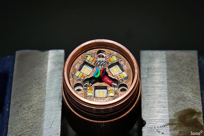
After soldering on the LED wires to the AUX board above.

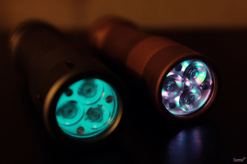
And finally, here's the Aux board in action, compared to a glow-gasket with my FW21. In this photo, I had previously used a green-yellow LED for the green channel. I since replaced that with warm white since I thought it came out better.

More to come soon.

Stay safe and healthy everyone!

It would be perfect, if you make variant to work with different color leds. As example, we could repower Sofirn IF25 with efficient Anduril driver. And any such flashlights in future.

Anduril has support for 3 aux LED channels, typically named R, G and B, but you can use whatever LED colour you like. Or am I missing something you're saying?

I find the choice of single colour LEDs curious. loneoceans, why did you find this solution best?

This board is getting better and better.

Great work!

Sofirn IF25 have two 2700k led and two 6500k led, so we can mix them by ramping mode. And 21700 onboard. Unfortunatly, UI is not anduril, proprietary, and driver d’t look very regulated.

So it would be nice to have high efficient Anduril driver, which can have two separate channels for two groups of different color temperature leds with ability to slide from one to another.

Subbed. :+1:

I appreciate the blue wire going to the G pin on the aux board, and the green wire going to the B pin. You rebel.

Hi loneoceans,

This is what we are waiting for... for the continued enhancement of FW3A, FW1a or even FW21. We are following the progress of your work. Thank you.

loneoceans. First of all awesome update on the project! Second, did you happen to see the PM I sent you?

I think D’AVerk is referring to variable CCT output. The IF25 is a two-channel quad that has WW and CW emitters. This would require duplication of the hardware I would imagine, and not a simple task on this size PCB. 4 layers and double sided architecture would be a requirement then I’d think. Unless there was a way to split the output via a PWM / duty cycle ratio between the two CCTs. In other words, boost circuit provides (e.g.) 3A total output. That current then flows into two linked FETs, where one is on while the other is off.

I could be way off base here, and likely am. I’d love to here your thoughts…

EDIT: :person_facepalming: I replied before realizing the thread had another page… Sorry folks

D'AVerk and JaredM, thanks for the clarification. Short answer - yes that's not a problem. I can definitely make a diver with multiple constant current regulated channels for tint mixing. I didn't know of any other common host which had a MCPCB for multi-temperature LEDs other than the BLF lantern, but the lume design is easily adapted for this purpose. It's also supported in Anduril. In fact, I reached out to the BLF lantern team if they were interested in such a design since I thought it would be ideal for both the large BLF lantern LT1, as well as the upcoming mini lantern. I got some positive feedback but no request to design one for it yet, so I guess we'll see how it goes. I would imagine that any sort of switching regulation would be ideal for a lantern, as opposed to using a linear driver, since long run-times and relatively low brightness is the typical desired scenario.

Thanks for your message, I did receive it and have replied. Thanks!

Ha yes a mistake while soldering the wires which I didn't really care about, since I was planning to swap out the green LEDs with some warm white ones later on. Nonetheless, good catch!

Agro, what do you mean the choice of single colour LEDs? Do you mean why I used single LEDs for the RGB array as opposed to using a single compact RGB LED? If that's your question, most RGB LEDs are common anode and would not fit the architecture on the board (as designed, without adding some small FETs for example, though this would remove the 'dim' mode for the AUX LEDs), and I had some other fun-colour LEDs I wanted to use such as pink and cyan, so I thought going for 18 individual LEDs would allow more flexibility. At the moment LEDs are arranged in 3 banks of 6 so you can only use 3 colors. Perhaps in a future design I can add series resistors for each, but it makes the board a little congested, as opposed to right now where it's quite symmetric and easy on the eye :).

Finally, I still have one question I'd like to ask BLF which I haven't found a solution for - anyone knows what spring Lumintop uses for the FW3A driver battery spring? I can't find one as nice as the one they have. The closest I can find is the gold plated qlite/105C 4.9x5mm springs but those are still a little too tall and don't compress as nicely as the conical FW3A spring (which also look to be silver plated?). Alternatively, any other good replacements you know of to recommend? Thanks!

I think the curiosity about the aux LEDs is because the current RGB aux Anduril flashlights like the D4v2 or FM1 can blend colors. For instance, the D4v2 can do yellow or magenta.

With single LEDs you could not do that; from many angles you would very clearly see R+G or R+B.