Let’s say you need an LED or a laser of a particular wavelength (color). Here is a very easy way to test your light source to see if it is actually what it claims to be. You can set it up in about 15 minutes using stuff you probably have around the house.
For this example, I’ll use some inexpensive 5mm UV LEDs purchased on eBay. The description says they have a wavelength of 365nm. (useful for curing photosensitive polymers for bonding, etching etc.).

So to test these LEDs, we can exploit the wave-like nature of light. You may have noticed the shimmering colors produced by a butterfly wing, or thin films of oil floating on water. This happens when light is split into many paths, such as reflecting off the microscopic layers of oil and water. The wing is covered in millions of tiny reflective scales. Those paths then interact with each other. This is called interference. Each wavelength diffracts and combines a different way and this forms patterns.

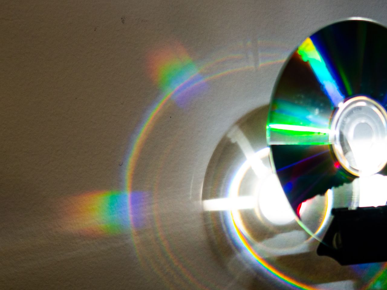
Compact Discs (CD) have grooves in them just like vinyl records, except these are much smaller. The grooves are separated by 0.000 001 6m. You could fit about 50 grooves onto the width of a human hair. We need the spacing to be this small, because it is close to the wavelength of light we are trying to measure. (UV-B = 0.000 000 365m) Because we know the precise spacing, and because CD-Rs are made of clear plastic, and are abundant, that makes them an ideal source for a “diffraction grating”. The diffraction will produce the interference pattern we want. Monochromatic (single color) light will be appear at a predictable angle. You can also buy commercially made diffraction gratings online for around $5.


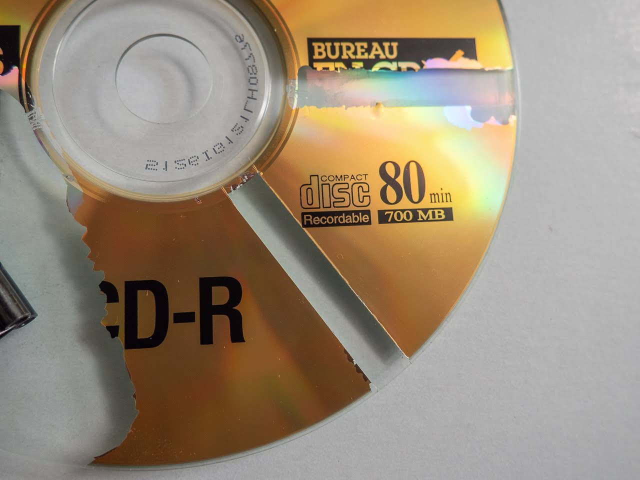
We just need to make a little window in the reflective foil layer of the CD-R for the light to pass through. I made two light parallel cuts on the label side, going from the center out to the rim. No need to press hard; You just need to get through the thin foil, not cut through the disc. Scrape away at the foil near the center to get it started. Next I cut a narrow strip of scotch tape and firmly pressed it to the foil. The tape should then lift away with all the foil.
If I tried to shine my naked LED through the CD, I would just get a smeared out blob. We need a very narrow beam so we can accurately measure the angle. If you’re testing a laser the this part is already done. I arranged two razor blades on a piece of scotch tape to form a narrow slit. I used a 3rd blade as a separator to create an even gap between them. You could use various other methods to do this. The idea is just to get a tight, even beam. I’m sure that poking a tiny hole in some aluminum foil with a pin would work too.

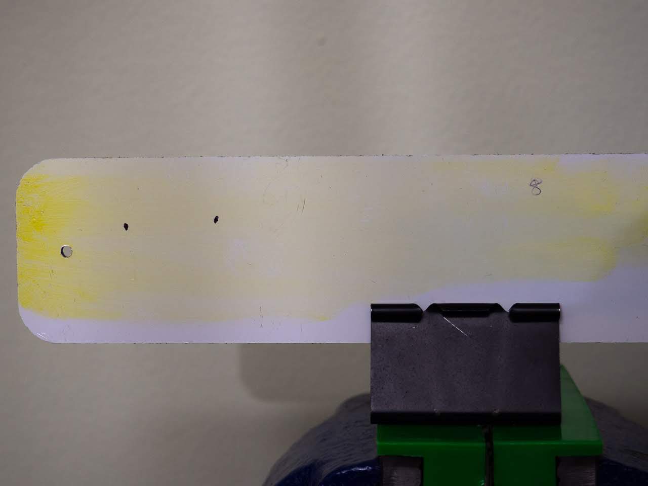
Now we just need a surface to project onto where we can measure the beam. I used piece of white plastic panel I had laying about. Because I’m measuring UV light, which is supposed to be invisible, I covered the surface of it with a yellow highlighter to make the beam show up brighter. If you like drinking tonic water, you could fill up a thin tube of it as well. Tonic contains the chemical quinine which glows a bright aqua blue in UV light.
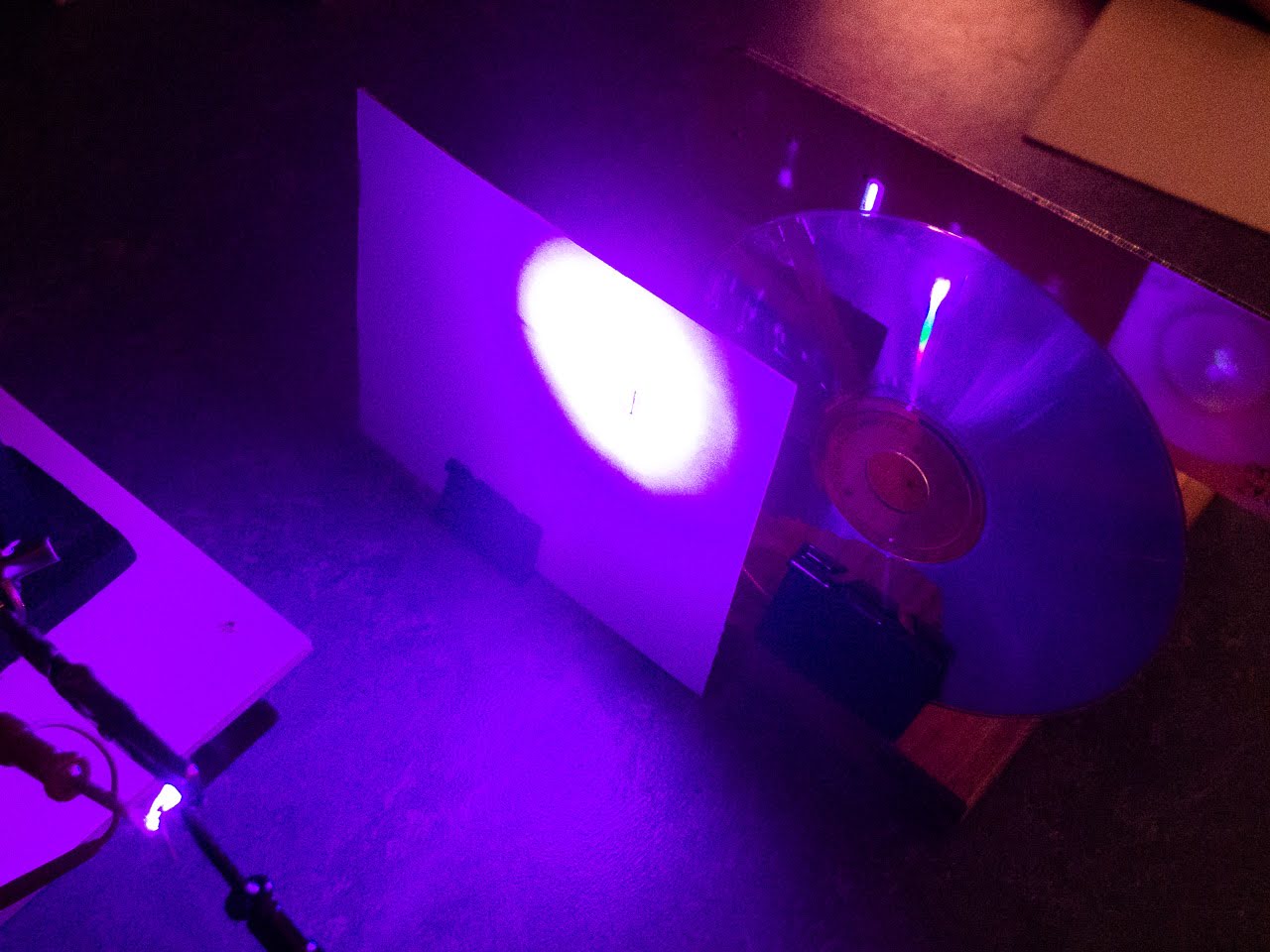
That’s all the prep you need! Now you just need to line everything up. Move the light source as far as possible from the slit so that you get very parallel rays. You can place the CD immediately behind the slit. You’ll want use the edge of the CD. The tracks there are straighter and not as tightly wound as they are near the center. Then place your display surface as far away as you can, while still being able to see the image. The greater the spread, the more accurate your result will be. The setup you see in my photos is fairly tight, because I need to keep everything in frame and because my LED has low output. I gripped my LED with a “third hand” tool. I put a bit of heat shrink tubing over it to only get the light coming straight out. (not necessary) The other parts are held up with binder clips I had in my drawer.

Play with the locations until you get the best possible image.
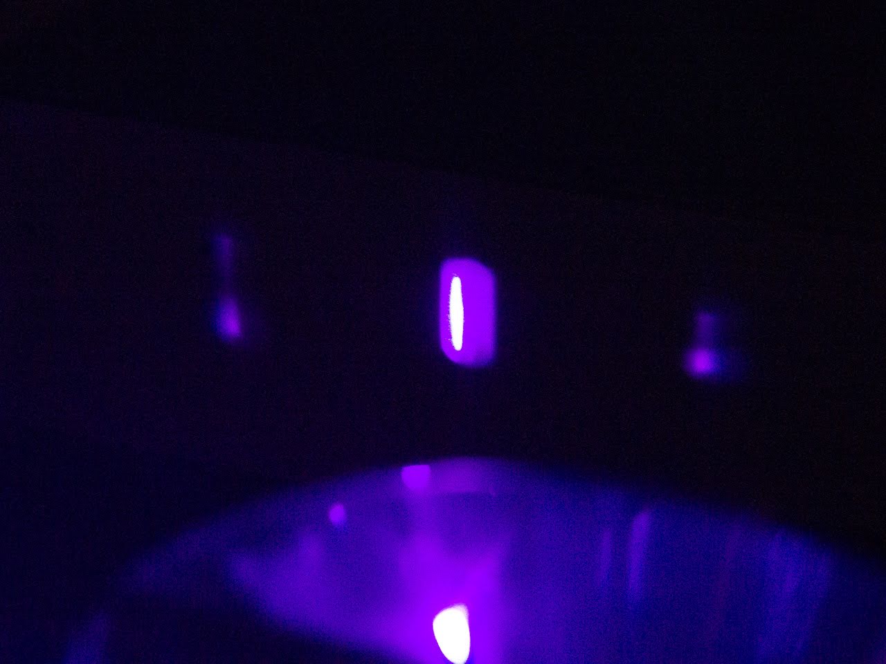
Here is a closeup of my white surface. The brightest image in the middle (mode zero) is at zero degrees off axis. Mark it with a pen. The next image on either side is (mode 1). Mark one side with a pen. That’s all you need. You may see more modes, each dimmer than the last as they get further from the center.
As precisely as your can, measure the separation between your two marks. Measure the distance from the back of the CD to the image. Try to get within 0.5mm. That’s it. If you’re a math whiz you can now use the arctan trig function to get the angle between your two images. Plug the angle, and the CD groove spacing (1.6 micron) into the diffraction grating equation to get your wavelength. If reading that caused your eyes to start rolling back into your head, then just use an online calculator:
Angle: http://www.carbidedepot.com/formulas-trigright.asp
b= surface distance, a=image separation, you want angle A
Diffraction: diffraction grating calculator - Wolfram|Alpha
click “calculate”: wavelength
slit separation: 1.6um
angle: from previous calculation
diffraction order (mode): 1
Here is the result from my quick back-of-the-envelope (literally) calculation:
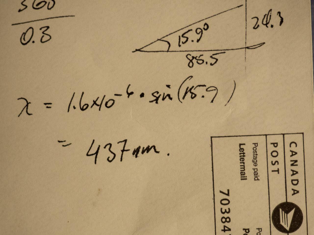
Even giving some margin for error, 437nm is pretty far from the advertised 365nm. Even before I set this up, the fact that the LED was producing so much light that I could see with my naked eyes (400-700nm) was a dead giveaway. When you spend $0.99 on a LED, you can’t expect it to be precisely engineered (however, I would expect the seller to be honest).
There you go. You just made a quick ’n dirty DIY spectrometer.