This is an Eye10 modded to triple N219b 9080 by pinkpanda
It arrived with the ball and spring removed, to eliminate the detentes on the dial. It had very light damping grease, and was totally smooth, like melted butter.
I decided to reinstall the ball and spring, after filling in the detente holes with JB Weld and repacking with heavy damping grease, Nyogel 767a
The heavy damping works well to prevent the dial from moving unintentionally.
However, I could still feel a slight feedback from the ball crossing the filled in detente holes, and the heavy grease prevented the one detente I actually wanted, at off, from working.
So, I took the light apart again, and removed the ball and spring. Now Im happier.
Nodded a cyan s2+ today
Nichia 219c , copper 1 cent as the spacer , fatter glass , it fits very nicely and doesn’t get as hot as the ylp t95 from where I got the nichia from
I’m surprised that it doesn’t get super hot with the bits I could use
I did things today, and yesterday. I managed to fix everything apart from the unfixable ti shelf. It became so good that this is the first titanium light to become my EDC.
1) the 10mA drain when off in the stock light was a guarantee that your battery is always empty when you need your EDC (and that it possibly drains your battery to death if you forget it a bit longer). So on the new driver I installed a 680 Ohm bleeder resistor, the two resistors in the tail that are inline with the tail leds were changed to 8.4 kOhm each and the leds were replaced by 485nm leds that are more visible to the eye than blue, btw at these low currents the colour they emit seems sea-green: a bit over 500nm to me. Also bits of aluminium tape were sticked to the sides of the switch to guide a bit more light out of the tail. The current when off is now 0.36 mA which is 30 times lower than stock and should last for 3 months on a battery charge. The amount of tail light seems a bit less than stock but is well visible in the dark as locator light.
2) the led was replaced with a 3500K 90CRI LH351D (from the batch I bought from contactcr) that I sliced so that the final CCT is about 3000K. I wanted to create a new customised ledboard but decided for the stock board, it seemed to me that the gains in thermal performance would not be high (at most from very very bad to very bad). I did very carefully apply a thin and even layer of AS5 to at least do something for the heat transfer.
3) the stock driver would have been fine if it did not have an ancient 2012-type user interface (memory without direct acces to low which is terrible for my EDC use, low is way too high, bad mode spacing) so it had to be replaced. The new driver is a Banggood BLF-A6 driver, my all-time favorite driver that is in all my EDC’s for years now. But since this host needs a 15mm driver I transferred the components from a BG BLF-A6 driver to a custom Oshpark board (designed years ago by wight, OSH Park ~ ), only the FET was replaced by a smaller LFPAK33-size FET (from Mtn). The edge of the driver was re-shaped to fit the non-circular cavity in the Tool AA ti.
4) the components and traces on the driver are fairly close to the edge, so the driver cavity was lined with a strip of kapton tape to prevent possible shorts with the shell. The stock driver was glued in place, the new driver is pulled in place by exact fitting short led wires, then clamped by the battery tube.
5) the driver board is a bit thicker than stock, which caused a small gap between the battery tube and head, with the disc sander I sanded about 0.5mm from the tube to close the gap.
6) (not visible in the picture because it was not done yet) after assembly the beam appeared to have a faint but annoying ring a bit outside the hotspot, it may already have been present in the stock light. The ring originates from light reflected from the side of the narrow reflector hole which has considerable thickness and is close to the led die so it catches some light. The solution was ditching the stock centerpiece, replace it with a standard “butterfly” type 3535 centerpiece and reaming the reflector hole to exactly fit the new centerpiece. The new centerpiece appears to give perfect focus to the domeless led and the beam is also perfect, a nice evenly illuminated but distinct hotspot (the way I like best) and perfect even spill.
7) I did not like the golden clip, and even the black clip of my alu Tool AA is not great, I do not use the clip anyway so it will remain clip-less and will make a nice custom lanyard from thin paracord.
Performance
A direct drive LH351D is easily too much for the heat trap that a all-titanium head is, so the tail spring was not bypassed and I used a yellow “3A” Vapcell 14500 instead of the “10A” H10.
In 4-mode setting I measured 6.5lumen~~65lumen~~>350lumen->650lumen. I have not measured current yet but my guess is that the 350lumen setting has about the same current as the 650lumen max of the stock XP-L2/driver, so already not really sustainable in this host. The 650lumen max in the new situation (guess=3Acurrent) is dangerously hot now, although I let the light run until the 40-second stepdown (built-in feature of the BLF-A6 driver) and that did not cause a meltdown yet.
The setting that I will probably use most is the 65 lumen. The light is pretty throwy so that already gives a fairly bright hotspot. Here is the hotspot tint at 65 lumen setting:
Summary of the tint: :heart_eyes:
I always wanted a titanium EDC, I had an Eagletac D25A and D25C once but I thought they looked not nice and the user interface was too complicated and mediocre. The Tool AA ti is pretty, very compact and has my ideal form factor, and now with a new nice led, beam, and my favourite driver I’m really happy and will check it out as EDC the coming period.
but, the low mode of 6.5 lumens with the new driver is not much different than stock… is that as low as the driver can go, or just your personal preference does not include a sublumen level? (I have a BLF A6 driven S41, and it certainly can go sublumen)
The Tool AA has a 12mm boot cap, in this size there is no clear one available, I only ever found orange. And I kind of like the black stock cap that does transmit some light although not very efficient.
Edit: I did manage to squeeze a 14mm clear cap in my aluminium Tool AA V2, with 6 slow colour changing leds on a ring pcb, the effect is cool but I think the cap is a bit too bulgy to look really nice:
It has the same led and driver as my ti version btw, but the driver is faulty (it has messed up lower modes but the 7135 is not the cause) either the BG driver was broken already or something went wrong with the transfer of the components to the new board (some Oshpark boards are less than perfectly fabricated). A new driver for that one is my next project.
Thanks. I set it on the group with 4-modes because that is how I use it most, but if set to 7 modes it goes much lower yes, I just measured it, exact 0.300 lumen.
I used to use a similar tailcap, a clear 14x6mm. I would usually ream out the hole, but still they would protrude too far to allow tail standing.
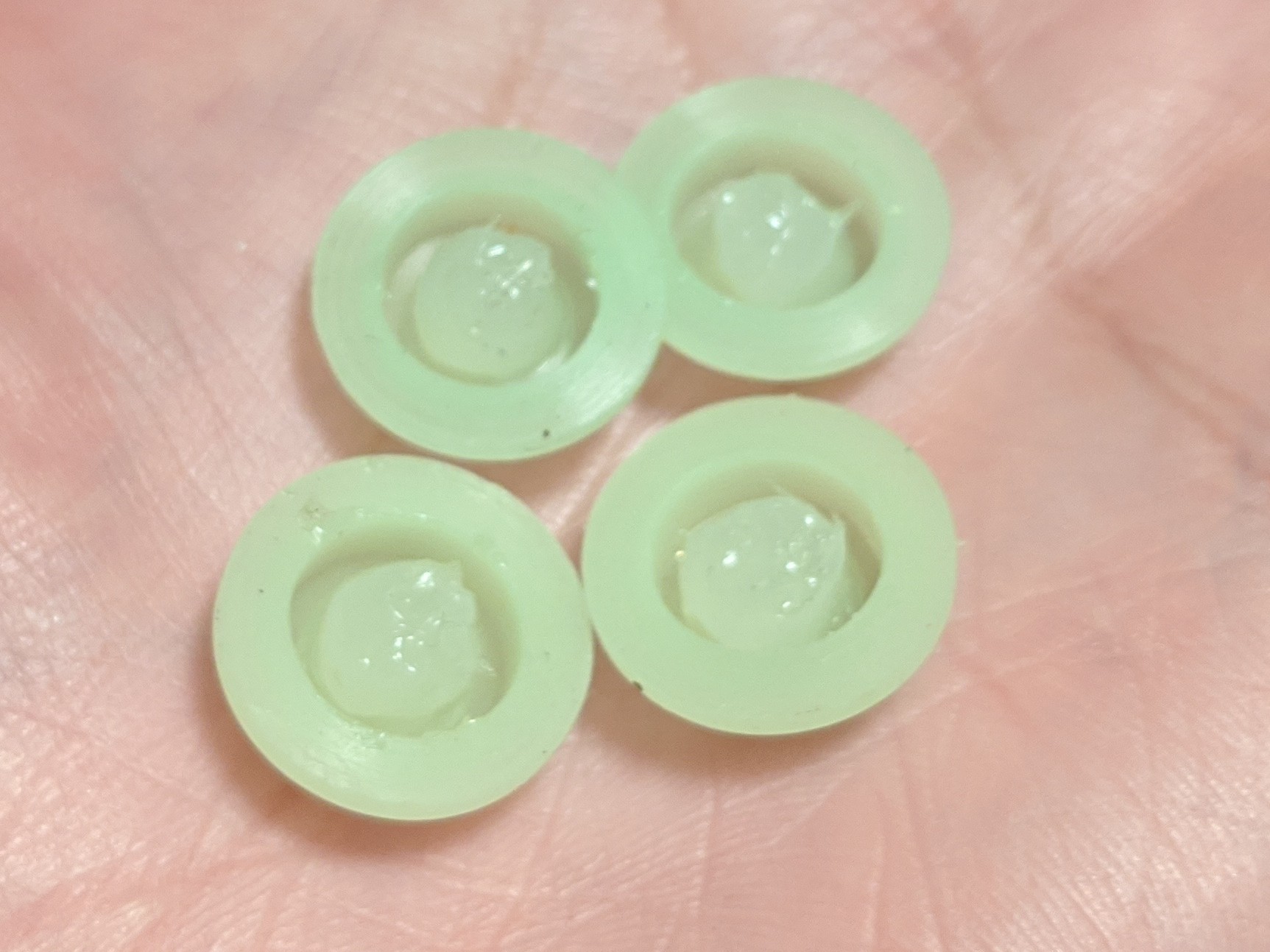
I switched over to these. They’re there right size and the “light green” ones let a lot of light through. The only problem is they don’t have the little post inside the tailcap so you really have to press the switch far. I address this by adding a dab of clear silicone caulk to the inside and then they work perfect!
A light green cap is not my perfect colour for the ti Tool or with the colour changing leds, but thanks for the link, they are good for some other mod in the future
On an other note: Ouch. I just measured the currents of my Tool AA ti, the 4 modes are 40mA, 320mA, 1.85A, 4.55A. I will be careful with the two high settings!
The lowest 0.3 lumen of the 7-modes group is 9.3mA. This is not efficient but it is at least by choice: parallel to the led, the MCU draws a bit over 2 mA, and the 680 Ohm bleeder causes a bypass of about 6mA. Still, it provides 4 days of continuous moonlight.
Mine has blue LEDs under on a ring board, so all I see is blue, not so much the green. But I agree, given the choice, green is definitely not my preference. Better than trying to shine a light through a black tailcap in my opinion, though.
The chance of the light from the blue leds getting its way out of the switch cap of my Tool AA Ti was low because of the leds lying so deep (the black-ish cap does not help either), so despite the leds giving off plenty light the effect is rather dim. I solved a lot of that by raising the leds towards the cap, using small pieces of wire, so that they are now flush against the transparent plastic ring. It makes the tail light at least 4 times as bright.
My advice: do not try this at home unless you are a soldering masochist like me . Instead go for one of the led ring pcb’s from Oshpark described and linked in the lighted tail thread. Much easier and likely even more robust.
(Can be watched as stereo pair, cross your eyes like you learned to watch those fun 3D books of the nineties)
Interesting... Been looking at the EDC18 driver, and the switch LED looks like 0402 size, and think all the resistors are 0402 as well - this is difficult for me to work with - need to mod the LED/resistor to work off of pin #7 instead of wired to Batt+.
Probably not, the used wire length is so short that when soldering one side of the wire, the other side unsolders, it is all about being quick, but being quick increases the risk of bad solder joints.
What would help (but I did not do) is using two types of solder, a high temp solder to solder the wires on the pcb, and a normal temp solder for soldering the led on top of the wires.
But still, use a Oshpark ring pcb and your life gets easier, you can even use 6 leds instead of 2 and play a bit more with colours if you are into that.
Reminds me of this 371D with the tiny aux led on the tower. It’s actually pressed into a hole in PCB and then just uses a snail trail of solder to make connection.
There is a newly announced version of this driver with motion sensing, light sensing, battery “testing”, double click support and more advanced UI options.
I like to use 0ohm resistors cause the ceramic film body doesn’t transfer the soldering heat like a bit of wire so it’s easier to solder each end without Desoldering the other.
You’re welcome sir! I’ve done it to my side-button sofirn lights (stock drivers) cause they like to use that black button with just the tiny bit of clear material in the center so getting the led closer to the base of the button is a big help.