MtnDon's Hand Made Class, 8th Annual BLF/OL contest entry

Yes, that reducer is a handy one. That type is not available everywhere. There are other adapters that do the same basic job and use less copper and are cheaper. I got those at a small hardware store.

.
.
Don’t ya’ll just hate it when you blindside yourself to something just because you fixate on the first idea that came to mind? First there was Plan A, then Plan B. Now I have Plan C.

Rather than try to carve material away to make a ledge for the driver to sit on, how about building up a shelf? My thinking went awry when I fixated on using one of the many 17mm drivers I have on hand. As we were eating dinner I remembered that there should have been a 20mm 8*7135 driver in the driver box. I had used it in a temporary thing and forgot where it was.

A 20mm driver will slip inside a 3/4” copper pipe very nicely. I’m using 3/4” copper, so……

So…. to start I cut off a 3/4” long piece of the 3/4 pipe, and secured it in the vice.

Next I had to remove a section of the pipe wall so it could be squeezed smaller and inserted into another length of 3/4 pipe.

I squeezed the section and inserted it, after about 3 attempts. My math calcs were about bang on for the section to remove. :slight_smile:

Pushed it far inside to provide a ledge of sorts…

I cut the outer pipe with the tube/pipe cutter at a position that would let me try both ends with different amounts of recess. Here are the two pieces with silver solder flux applied.

After heating with the butane torch and applying some silver solder…

Here, after cool down, is a trial fit of the 20mm driver…

The assembly has been cleaned up. Here it is with the driver. This driver even had the firmware I wanted, Crescendo. Saves the time to reflash it. For the purpose of this project I may remove a few 7135’s. This light is not intended to be a barn burner. I have not decided for certain yet.

I think Plan C is the winner. I guess we will see how that goes. :slight_smile:

Hey now, our shelf ideas are starting to overlap! :smiley:

It might have been your mention of a 20mm driver that caused the wheels in my head to mesh? :smiley:

I have 6 or 7 assorted 17mm 7135 drivers so it just seemed right to use one of them….

Yep, every time I go to the hardware store, just have to shop around for ideas, LOL. Wife always curious just what I’m looking for so I tell her just looking for things I may need for whatever. If you have parts available in your mind, you have options for putting together or fixing things, not always flashlight stuff either. Nice work around a problem. :+1:

Nice to see a start MtnDon. :+1:

Good luck and good work MtnDon :+1:
Looking to learn in this :nerd_face:

I ignored some things I could have, maybe should have, done today and used an hour or two working on this. :slight_smile: :person_facepalming: :question:

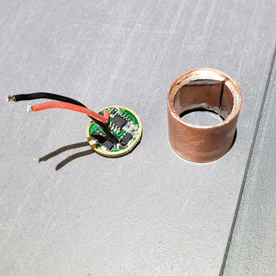
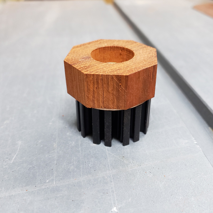
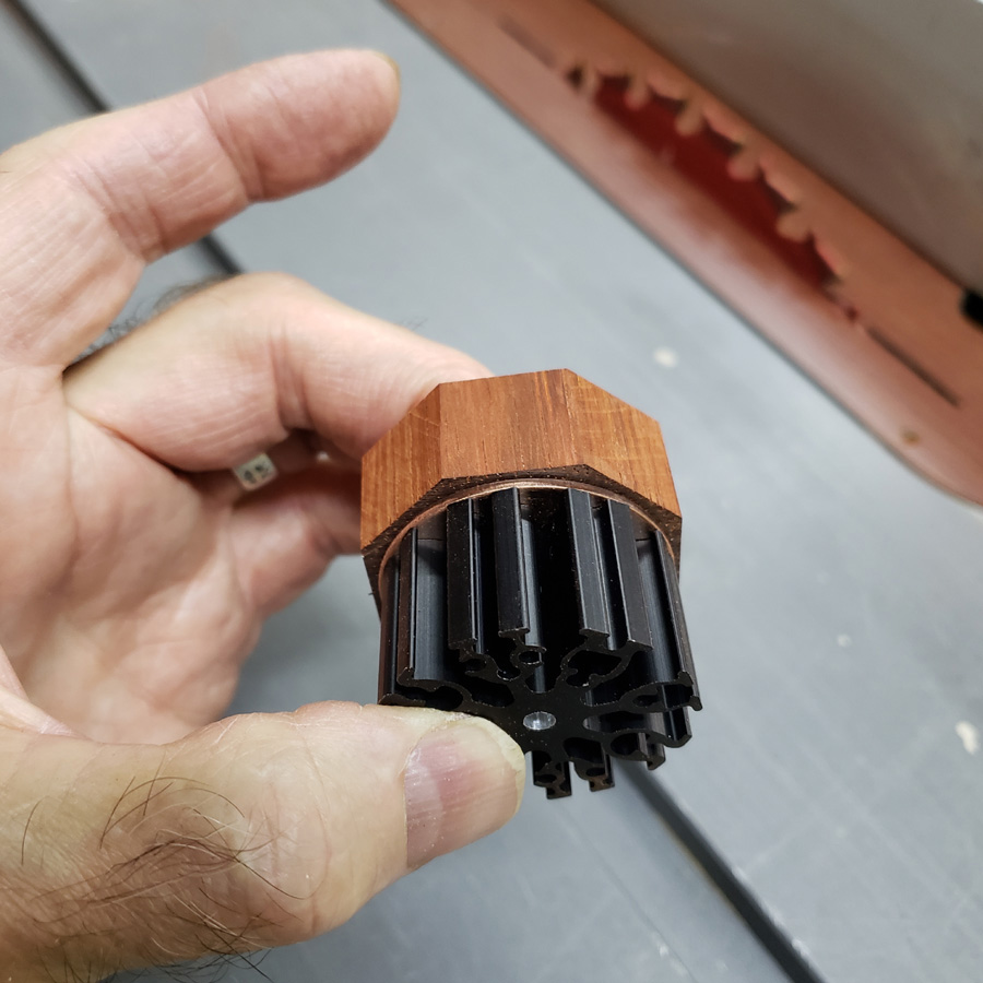
Okay, when I made the previous piece, a pill-like thing, I made 2 different depths to the shelf, one on each end. I decided which end was best suited to the task. I wanted to cut or grind the other end down to remove the ringed shelf inorder to have more contact area between that side and the copper disc it would be mounted on.

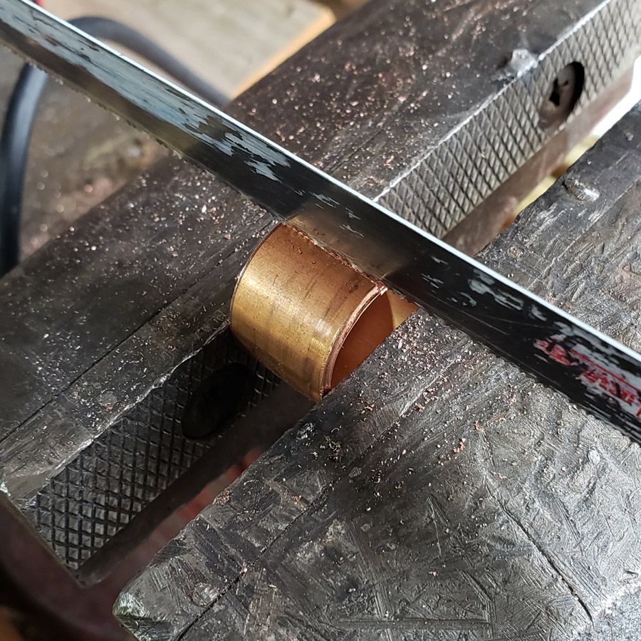
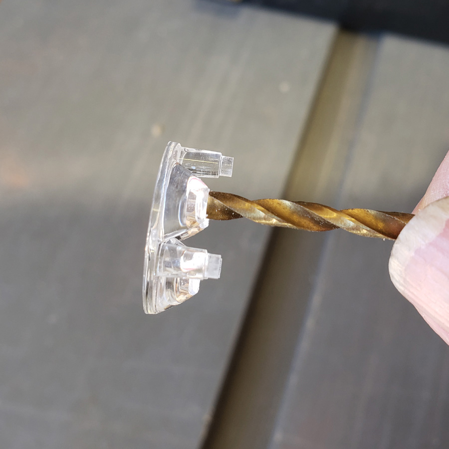
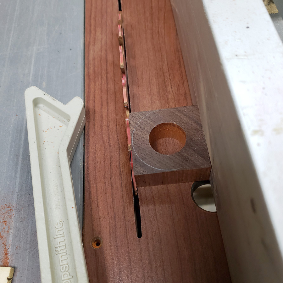
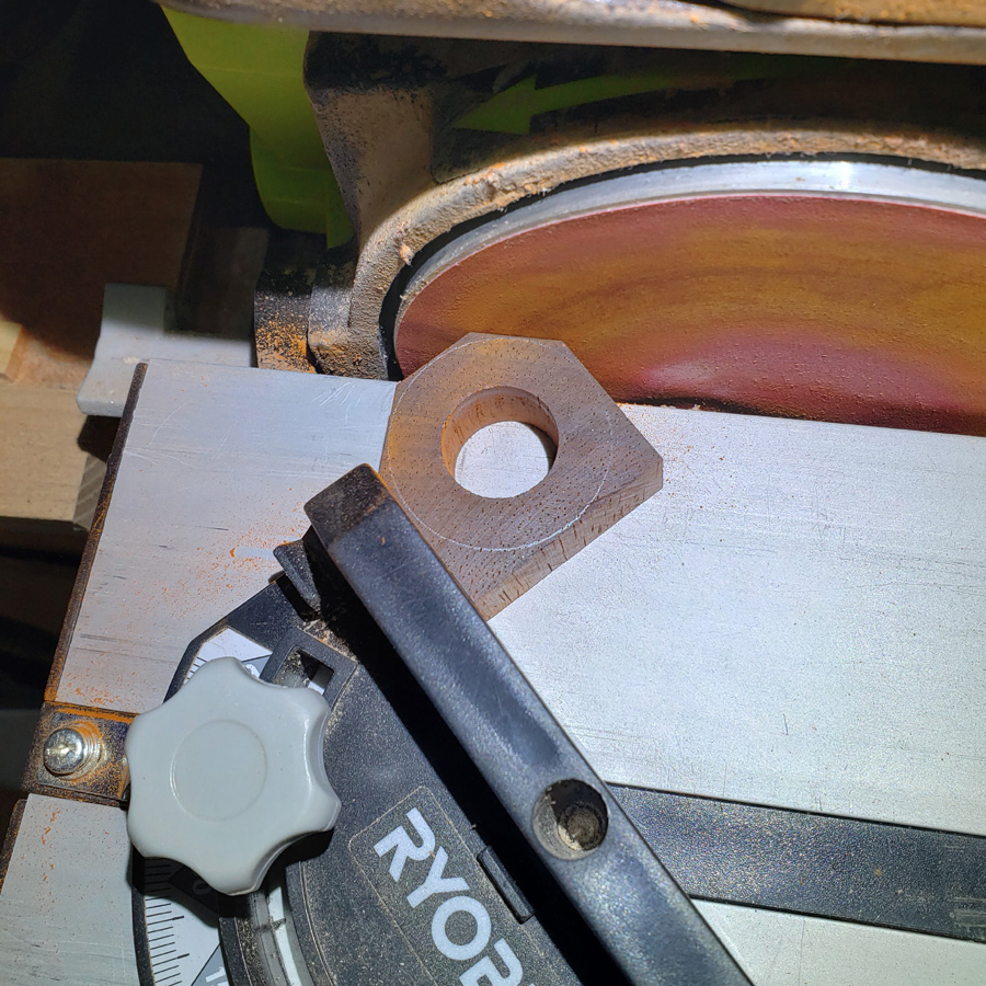
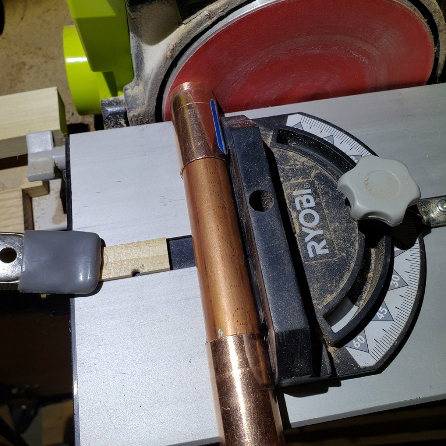
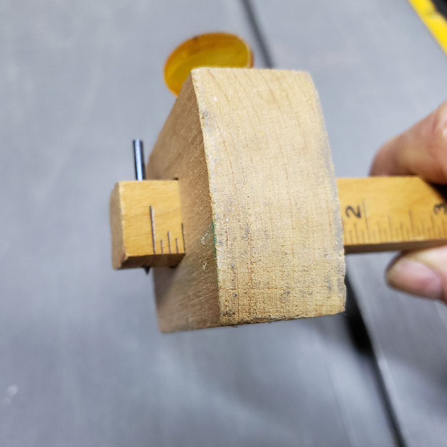
There was not sufficient material to be able to use the tubing cutter. Cutting off with a manual hacksaw never results in a 90 degree cut. Trying to use the chop saw was too dangerous on a small piece. So, I opted to grind and sand it down. The preliminary rough material removal was done on the belt sander (180 grit), hand held and eyeballed. I then squared up the disc sander table and miter gauge (cheap thing that it is) as best as I could using a metal square that has proven to be accurate. The picture below helps explain my process. The “pill” is slipped inside the copper coupler fitting closest to the sanding disc. The length of 3/4 copper inside that coupler is pressed against the “pill” to press it against the sanding disc. The second coupler is there to keep the pipe assembly parallel to the table and miter surfaces.

Rotating the copper tube while moving the assembly forward to lightly touch the rotating disc (220 grit) slowly removes material. Only allowing the copper to touch the disc whie the copper is being rotated allows a near perfect 90 degree end to be sanded to the copper pipe end. That is my theory anyhow. If anyone has a better idea I would love to hear about it. Short of chucking in a lathe, of course.

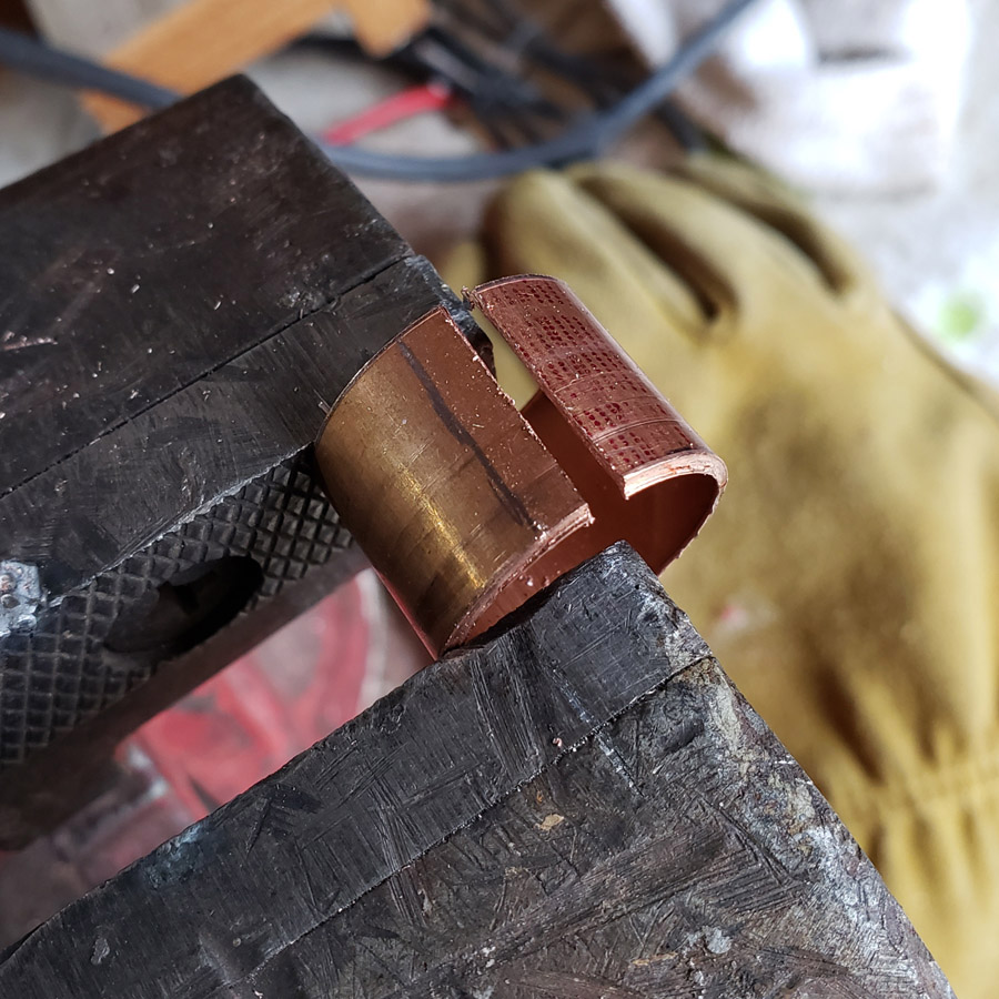
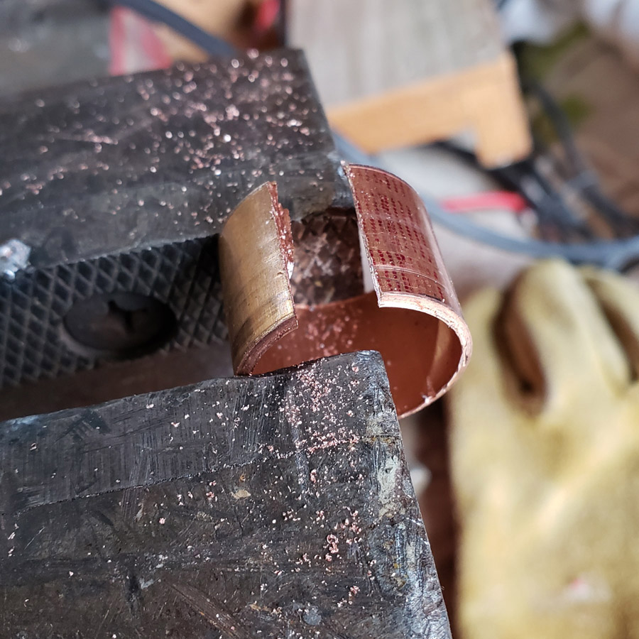
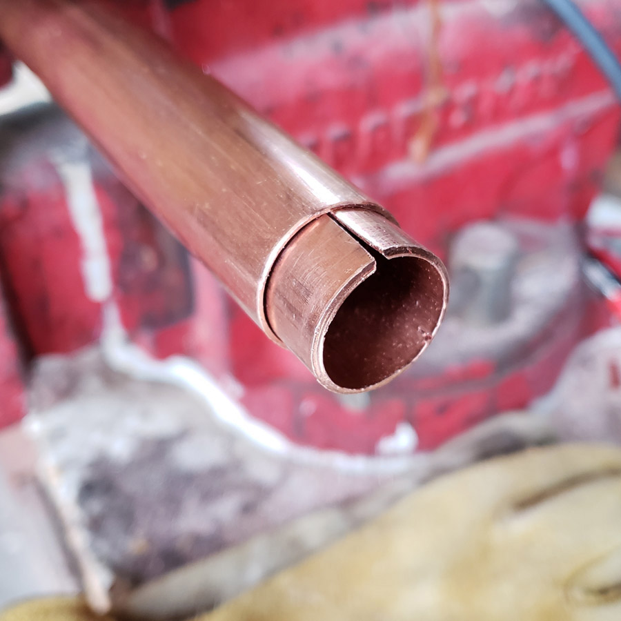
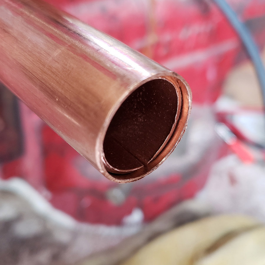
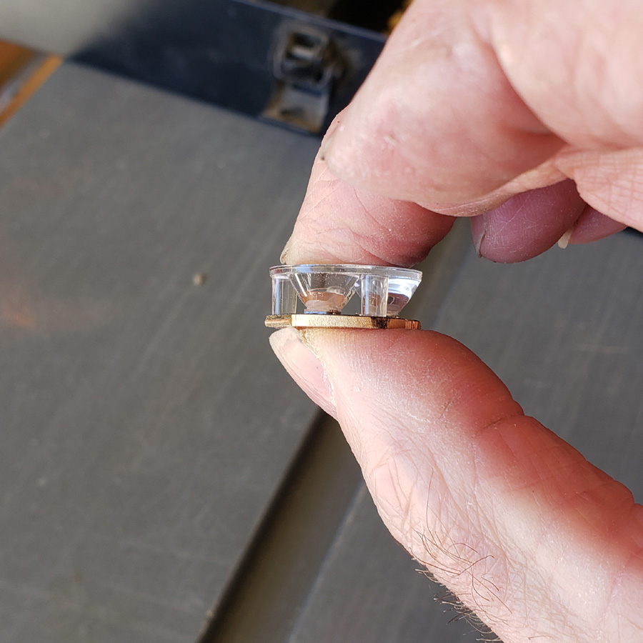
The end appears to be reasonably square…

There is a slight gap between the collar insert and the pipe, but the inserted part is well soldered as trying to pry with a small screwdriver blade resulted in no movement.

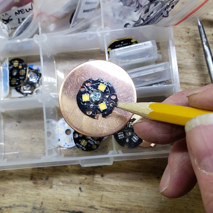
Next we see a 1-1/2” copper disc. Old Lumens used to buy copper from Bopper Metals and so do I. That is 14 gauge, about 0.085”. The yellow plastic thing is a center finder. I thought I would show it just in case some viewer is not familiar with one. The work piece that you need to find a center on, is held in the vee and a line scribed. Rotate the work 60 degrees or so and scribe again. Repeat. There should be 3 lines that intersect at a single point. If not, try again. Maybe the work is not a perfect circle or something went wrong holding the material in place.

If you look carefully the three intersecting lines can be seen.

I did pretty good marking the center point with a very pointy awl.

I then drilled a hole in the center. Sorry, but I missed taking a photo of that. You will see the hole later.

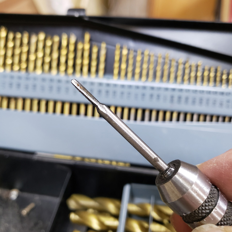
A marking gauge was used for the next step Here’s a photo of the tool…

The pin is steel and is ground to a chisel edge. The block slides on the shaft and is locked in place with a set screw. It is usually used to make a line parallel to a straight edge on a board. I used it in a circular fashion.

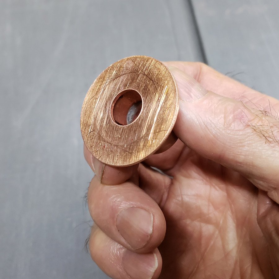
The “pill” is to be silver soldered to the center of the copper disc. One method to center it would have been to drill a large hole, just lage enough to fit the “pill” into, but I do not have a large bit the right size. I calculated how much rim there should be all around the “pill”, set the marking gauge to that and scribed a series of short lines around the circumference of the ciopper disc.

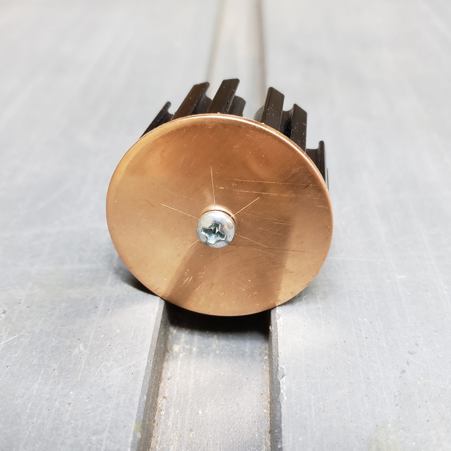
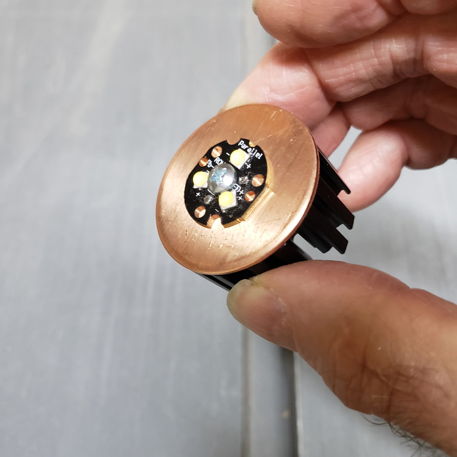
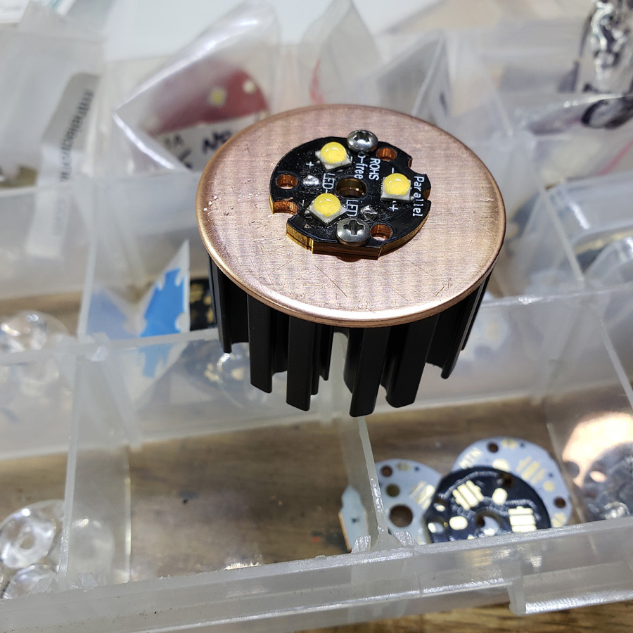
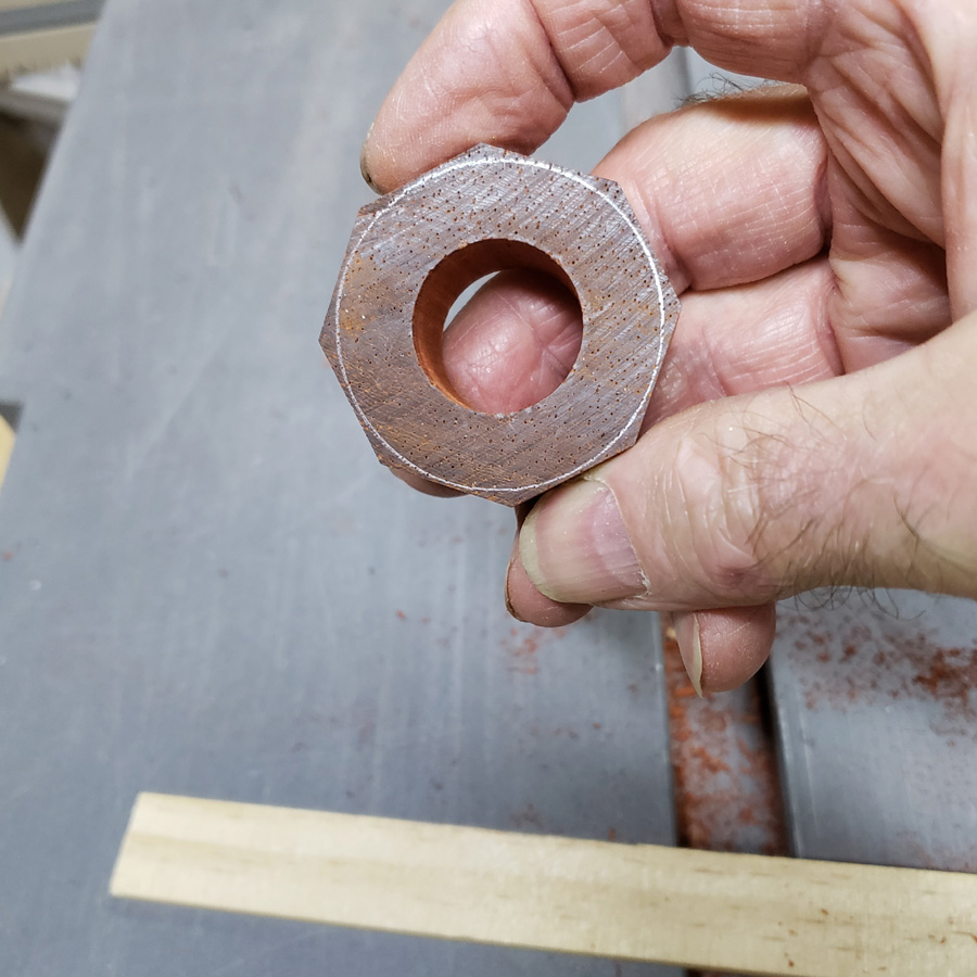
I forgot to photograph that at the moment I did it. When I realized my error I scribed the reverse side of the copleted assembly to illustrate the scribes. The drilled hole is also seen. It is needed to pass some wiring through.

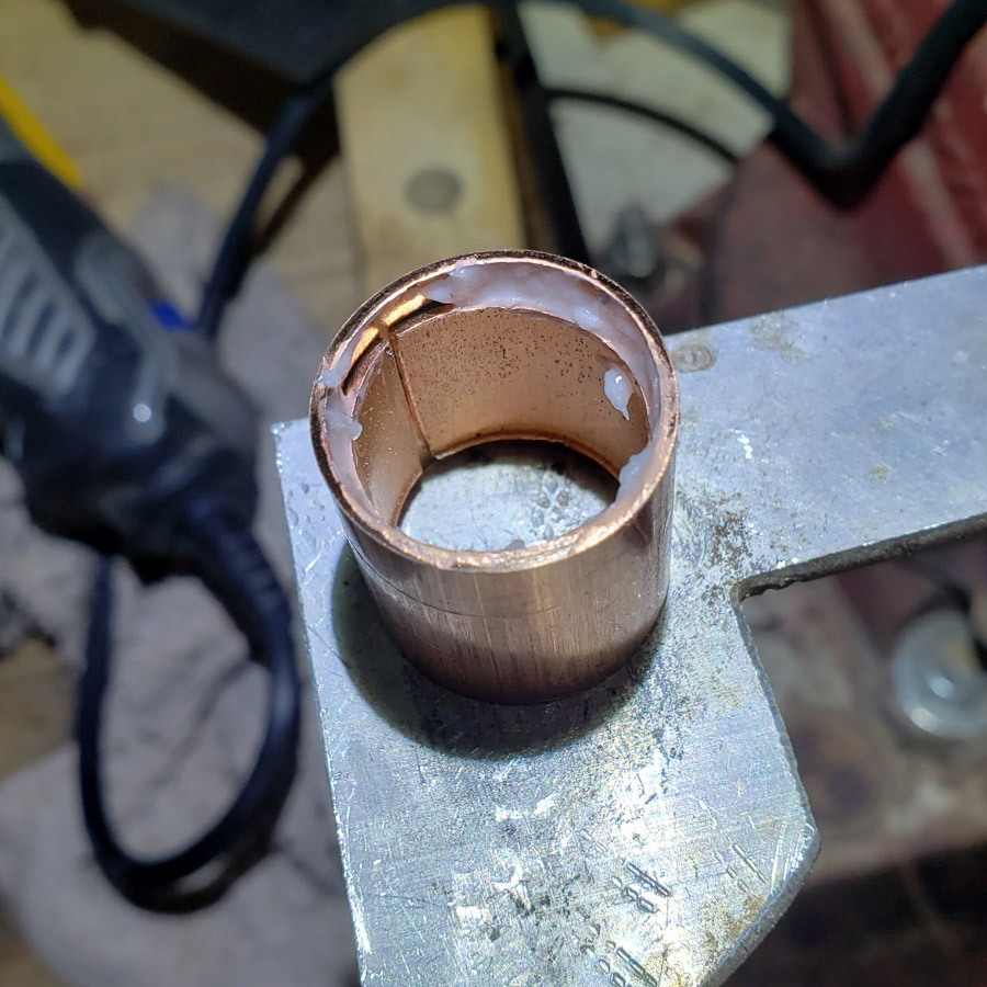
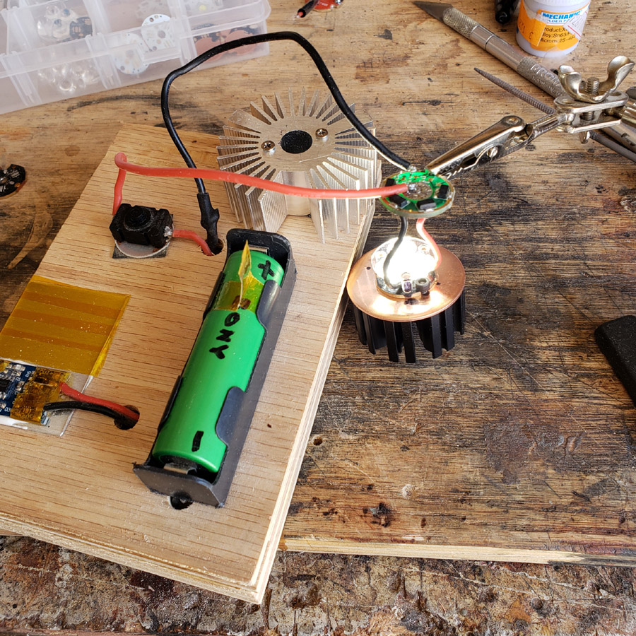
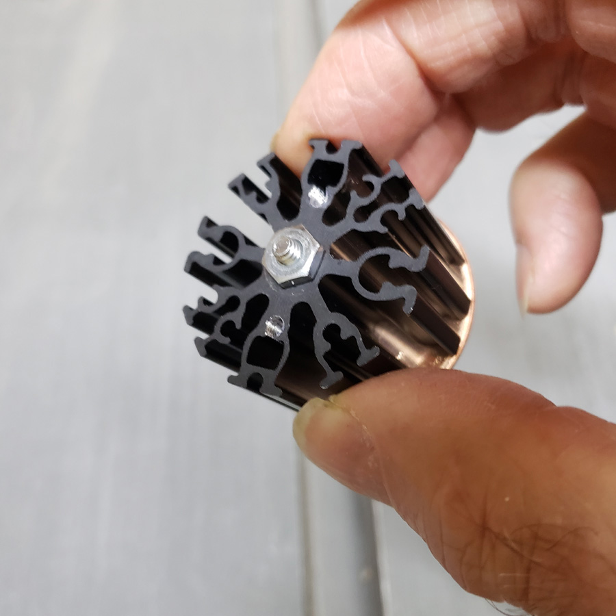
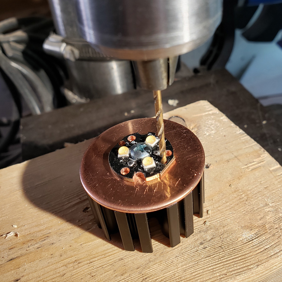
Next a real challenge. The “pill” is to be soldered to the disc, centered as accurately as possible. When the parts are fluxed and heated the too parts can easily slide out of placement. Touching the loose part with solder wire can also shift the alignment. I decided to try clamping with a steel C-clamp. I thought my torch could put heat into the parts faster than it would dissipate. I hoped so at least. Here is the clamped setup with the clamp held in the vice. Flux has been applied.

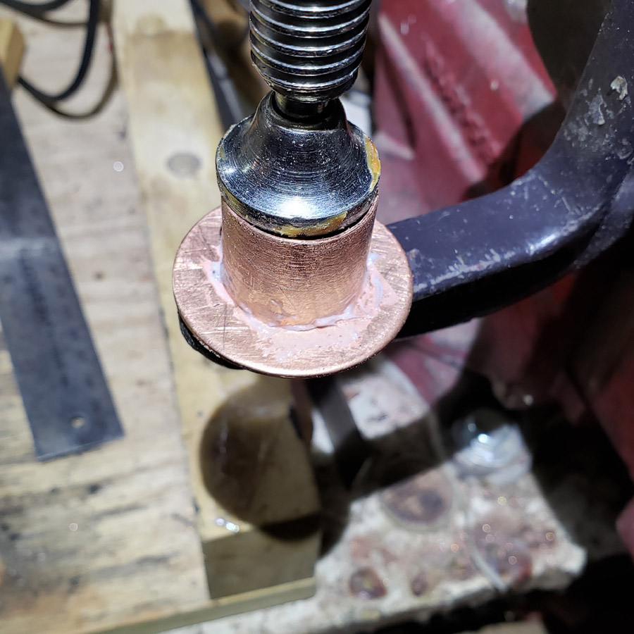
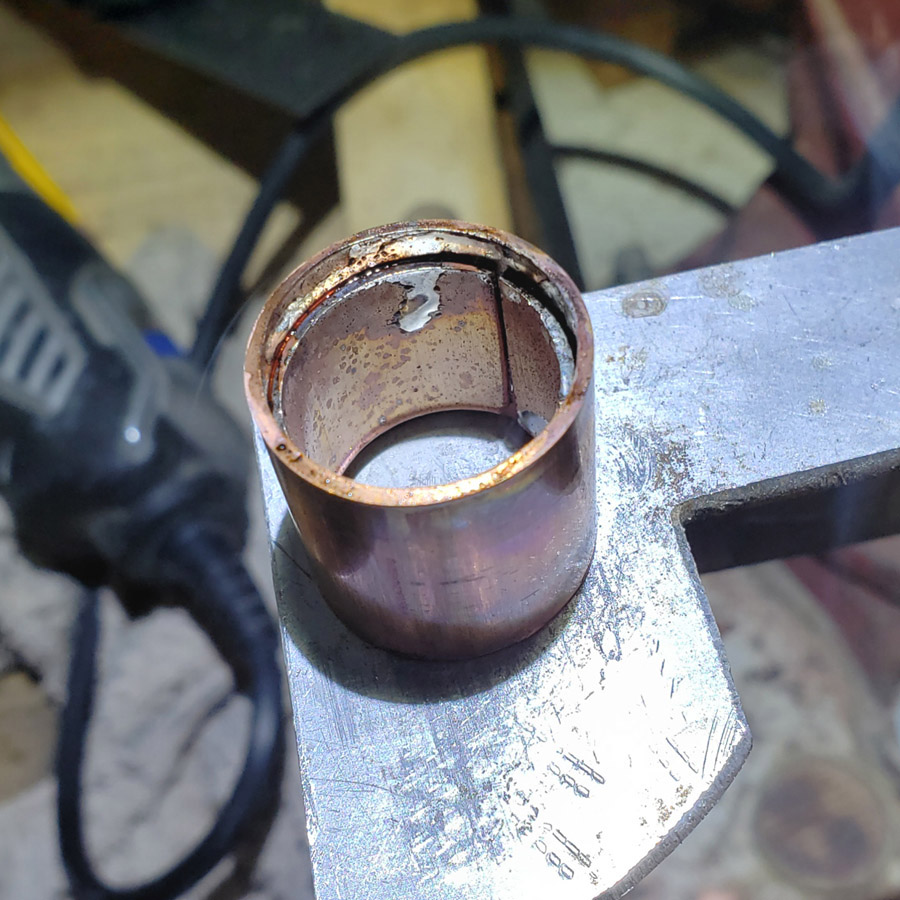
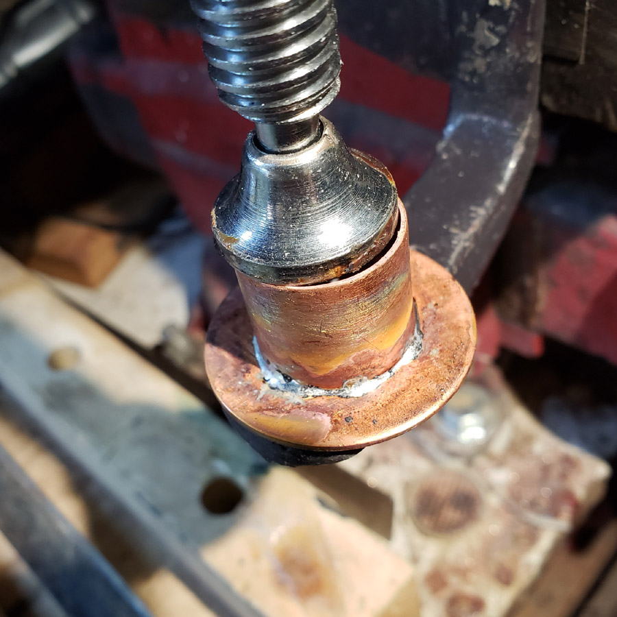
The torch heated fast enough to melt the solder nicely. I cut small pieces of the solder wire (1/8” long maximum) and positioned several around the joint. I placed 6 such pieces of solder and neglected to take a photo before heat was applied. Here is the soldering taking place…

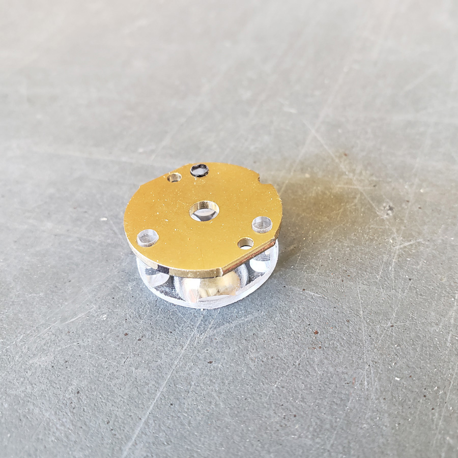
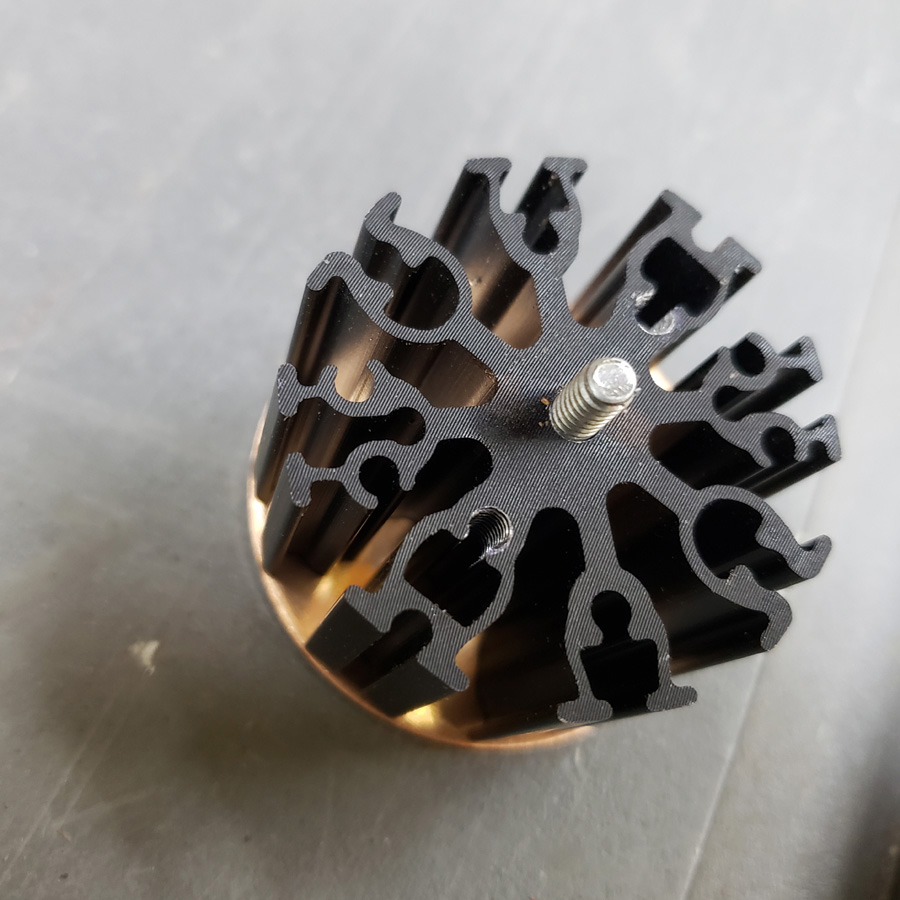
…waiting for the parts to cool off… the soldered joint appears to be solid.

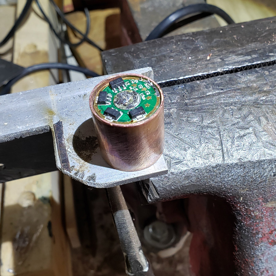
Here it is after being washed of the flux residue. Note the solder that has wicked under the edge of the pill on the inside. That wis from molten solder being drawn into joint by capillary action. No solder was applied directly to the inside of the pill-disc joint.

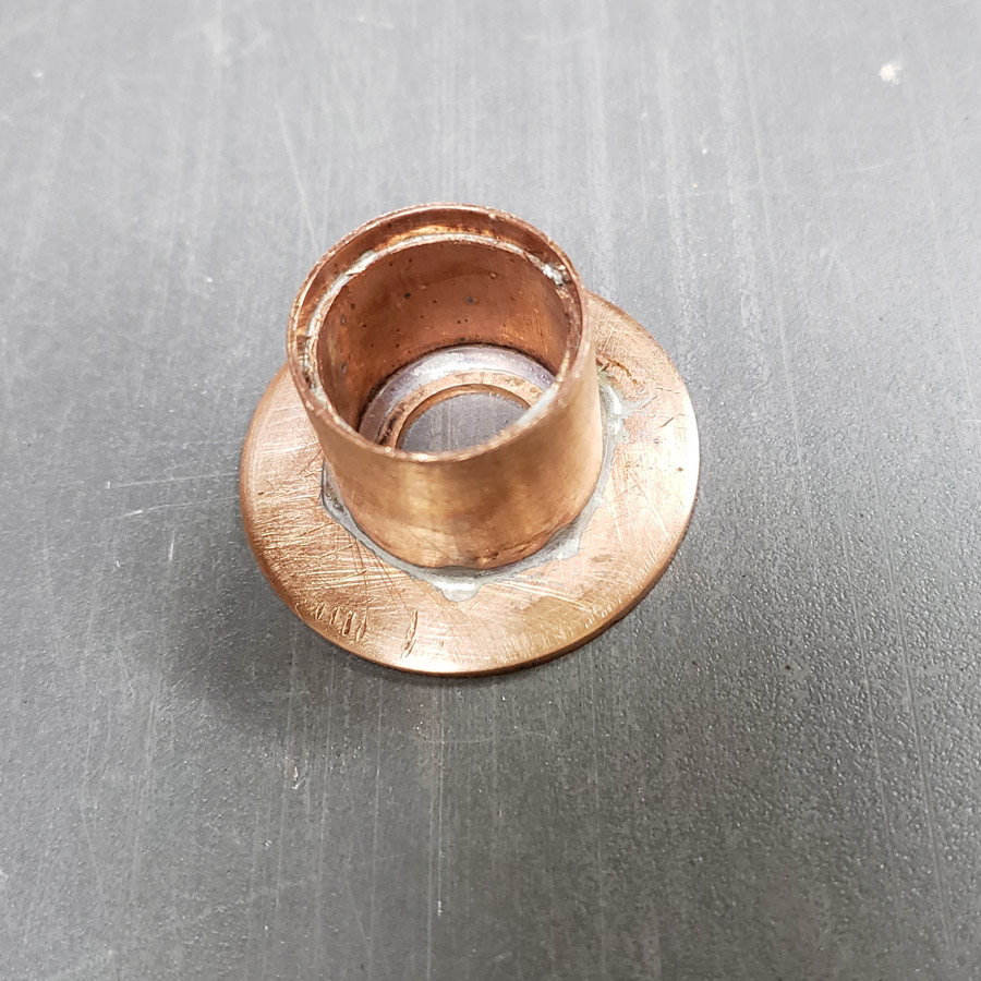
I am happy with how that worked out.

How hot did the copper get on the belt sander? I hate grinding small bits of copper when your hanging on to it with bare fingers.
Funny wooden mallet there Don. Think you need to reposition the nail to hold the head on. :stuck_out_tongue:

Hot! I kept dipping it in a can of water. The belt is wet/dry, though very wet saneding it “out” because the the electric motor. :wink:

The head is replacable so I can switch to a prettier wood, a plastic or even a lead head. :wink:

Really nice work, MtnDon. Very precise and clean. :person_with_crown:

Much better than a pre-made pill but also more challenging.

This light may be a little unusual in some respects. I guess all my entries in this annual event have leaned towards the unusual.

This aluminum heatsink will be incorporated. It is made by Wakefield-Vette. 38mm in diameter, it is 20mm in height.

The copper disc was drilled to permit mounting the mcpcb to the copper disc and the copper disc to the heatsink.

I reflowed the LH351D’s to the mcpcb before I had filed the notches needed to mount the mcpcb to the heatsink. :person_facepalming: Fortunately I was able to file the new notches without damaging anything. There are many combinations of mounting holes in the heatsink, but none match up to the mount holes in the KD mcpcb.

The led’s are 5000K, CRI90; I had them on-hand, left-overs from a previous project purchase. So far, everything I have used for this are left-overs from something else, or parts bought previously and never used due to a change of plans, except for the copper couplers

4-40 screws hold the peices together for a test fit.

That is a mcpcb from Kaidomain I bought some time ago. I had one of the KD optics that came with the triple red mcpcb I used in last years contest entry. When I bought the KD triple mcpcb’s I was not aware that the optic they use is slightly different from the Carclo ones. Anyhow we’ll use it here.

I did test fire it and it worked fine. The 20mm driver was from Convoy, bought a few years ago and used briefly in some other project before being swapped for a different one.

That may be all the work on this for this week.

Thanks for looking in.

Great work Don :wink: As always :wink:
And now I realized that the idea I was having for an eventual entry is somehow going on the direction of yours, so I will probably refrain from entering (not only because of that though, time, skills and available resources too)! :wink:
Keep it up :blush: :beer:

Looking good Don.

:+1:

You got us on the hook again Don :sunglasses:
Great photography too, :+1: Are you using incandescent lights for pictures ? I tried led lighting and it comes out unusable.
.
I just purchased a Cannon camera and still playing / learning to use it.
.

The lighting is mostly the LED workshop ceiling lighting. They are 5000K strips (50 cm long, 12 VDC run off of a few 12 VDC power supplies fed by the 120 VAC house power.) I bought from some seller on Aliexpress a few year ago. Some of the pictures were done with illumination from a cheap zoomie. That has a 5000 K LH351D I swapped in. The photos have all been taken the lazy way; using the camera in my Galaxy 9+. I’ve been using it for most photography for the past 2 years, except for landscape photos when the camera is simply not at its best. Then I use my venerable Nikon D200 or my Panasonic ZS100.

This project will end up looking more like a standard flashlight than any other contest entry I have done, but with some different touches. :wink:

Looking great, Don!

I have made some progress.

First though, I noticed a couple of problems. The optic legs stick through the mcpcb, so the optic did not seat fully. I thought this was a problem so I sanded the legs shorter so nothing protruded. I am currently not sure if I did the right thing. I has not used a KD triple mcpcb with one of their optics before.

The next issue was that the optic would still not seat fully. Close inspection revealed the portion of the optic that fits over the emmitter did not go as low as it would if the optic was used over a Cree XP-E triple. This project is using the LH351D Samsung. I pondered wheyher or not to slice the domes or to modify the optic, reaming out the “socket” a little. I elected to mod the optic. I used two different sizes of number bits and carefully turned them just using my fingers. I removed just enough material to allow the optic to seat fwith the three legs down against the mcpcb. I also considered drilling clearance holes in the copper disc.

I have not yet wired up the led to check the beam. Hopefully I did not ruin it.

So that was one issue. The other thing I oticed was that I had a slight concentricity problem between the mcpcb and the heat sink as well as with the copper disc that is mounted between the mcpcb and heatsink. The runout was not great but was enough to create possible problems with the next step.

I has a spare copper disc and a spare heatsink though. So I decided to redo this portion of the head assembly.

This time I used a different approach. I first found the center of the copper disc. Then drilled a center hole that matched the diamter of the center hole that the factory made in the mcpcb. I used that drilled disc to determine the point to drill through the heatsink center. The result was just about as perfect as could be when using the tools at hand.

The next issue to correct ws my chosen method of fastening the mcpcb to the copper disc. The previous method relied on using a pait of factory holes in the extrusion that were close to, but not perfectly matched to the notches in the mxpcb. Instead of doing that all over I decided to use the two smaller holes in the mcpcb. The pencil point in the next image indicates the hole pair I mean.

I used a machine screw to secure the mcpcb to the copper disc and heatsink.

I then drilled a clearance hole in the support wood block and proceeded to drill a dimple in the copper plate, using the holes in the mcpcb as a template.

I just barely marked the copper using the drill press. Then disassembled the three pieces and drilled a #50 hole through the copper for the 2 mounting screws.

The holes were hand tapped with a 2-56 thread.

The mcpcb is secured with two 2-56 pan head machine screws.

The heat sink does not have sufficient solid metal in the central area to tap into the aluminum body of the heat sink. The two screws penetrate the copper disc and protrude into a pair of the extruded voids.

Now I am happier with the mcpcb, copper disc and heatsink assembly and am ready for the next section. That’s coming up in the next post.

This next section is a test. It indicates the dirrection this part of the light project is taking, or at least what I am thinking.

I cut a small piece of padauk of a scrap and drilled a 20mm hole in it using a metric forstner bit that arrived from an aliexpress seller yesterday. I bought a small set of the metric bits and they shipped from a US warehouse; only took a few days instead of many weeks, maybe 2 months. The 20mm hole is to fit over the optic and the mcpcb on the front end of the light.

I then used the table saw to trim it down close to the outline of the copper disc making a square shape.

So there is a square. I want an octogon. I elected to sand the corners down to make an octogon, using the disc sander and miter gauge.

There. Looks like a big wood nut.’

Here is the “nut” fitted over the mcpcb and optic. The optic is a snug fit which is great.

So far, so good. It appears to be feasible.

That is about it for now. Thanks for looking in.

Looking good Don!