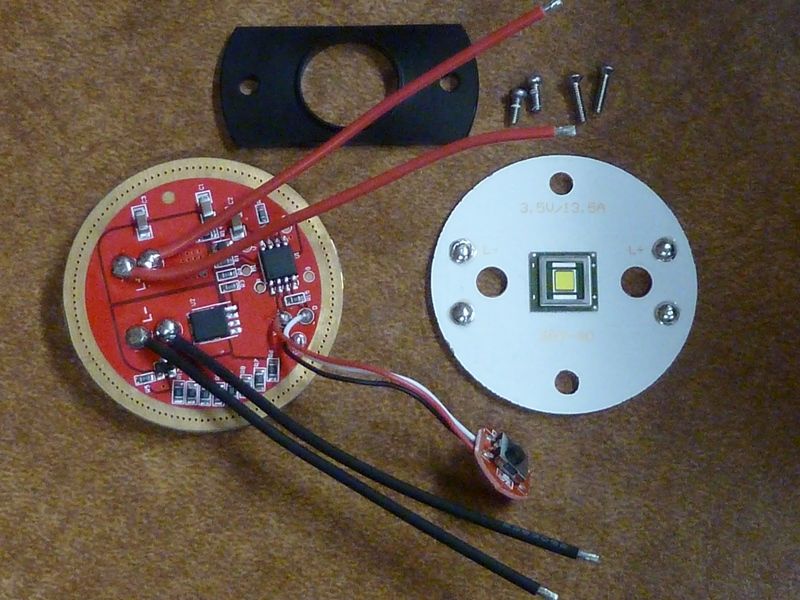
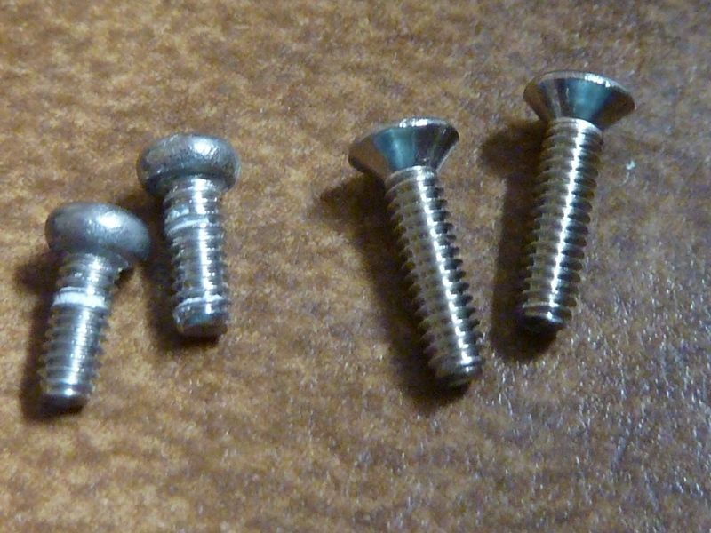
Driver, MCPCB, and centering piece. Shown are the shorter stock screws and the longer ones I chose to use instead - Phillips flat head 2mm x 0.4mm x 8mm. The heads fit snugly in the centering piece hole, holding it down with modest pressure.
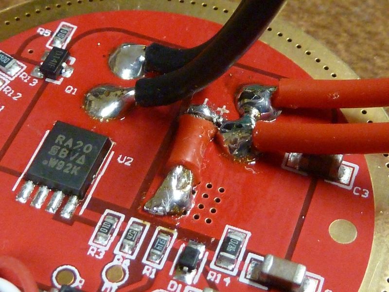
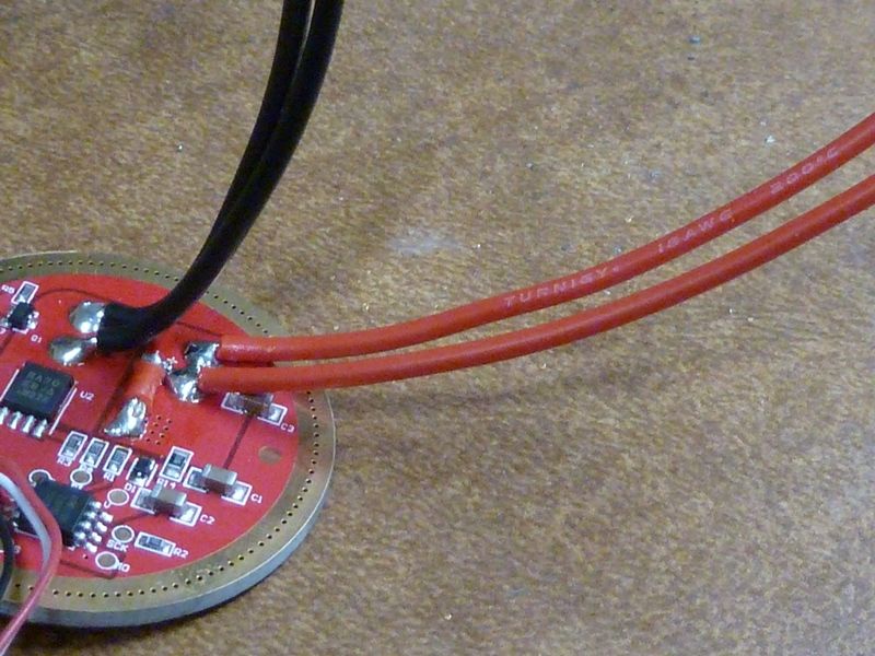
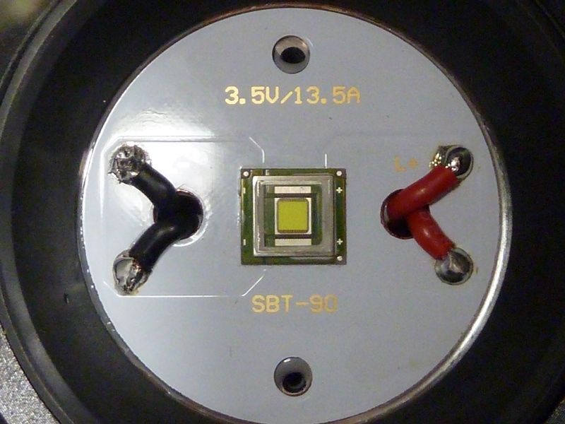
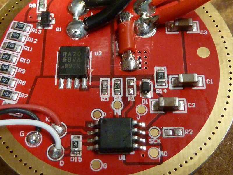
The FET is the SIR800DP - not sure if it's a clone or not. The wires are 20 AWG which I decided to stay with. Because they are doubled up, it's probably equal to a single about 18 AWG.
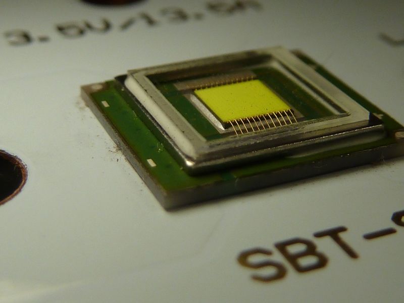
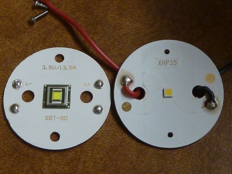
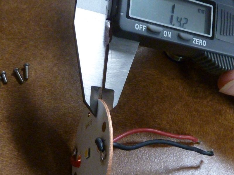
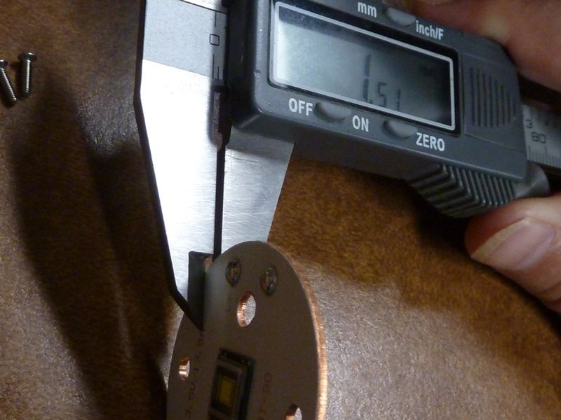
Compared to stock, same width but the 90 is slightly thicker which is a good thing:
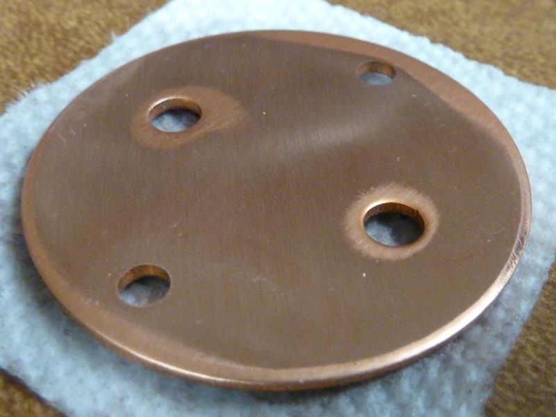
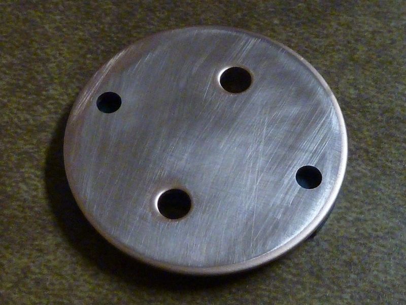
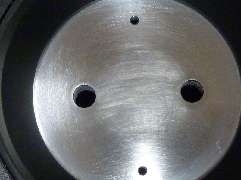
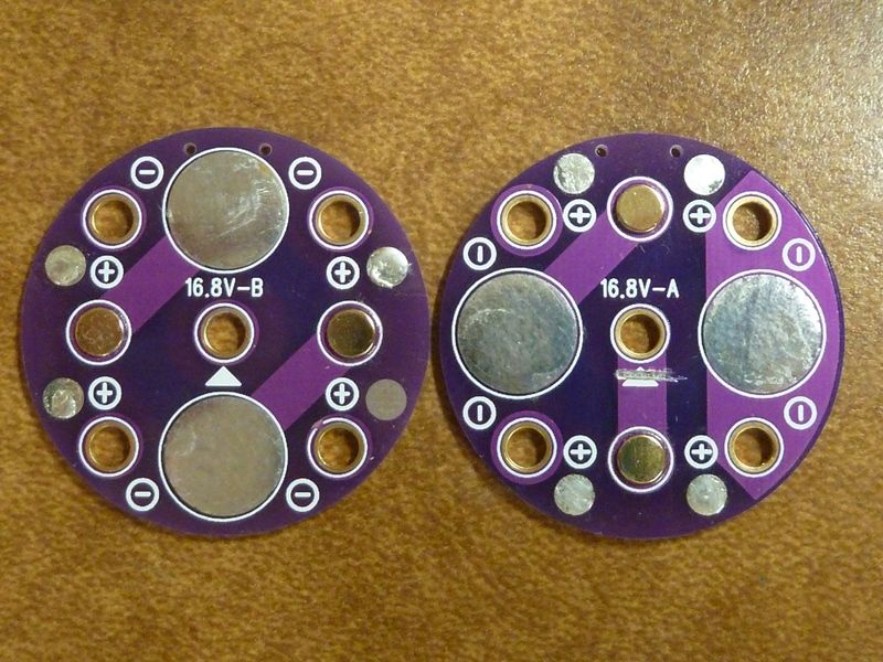
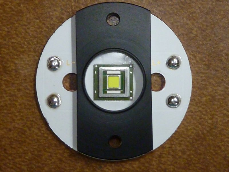
With oversized holes, it makes it impossible to center the LED from the centering piece alone:
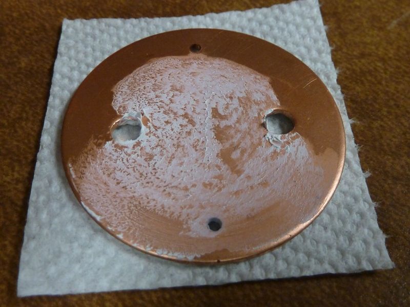
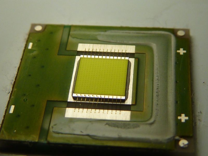
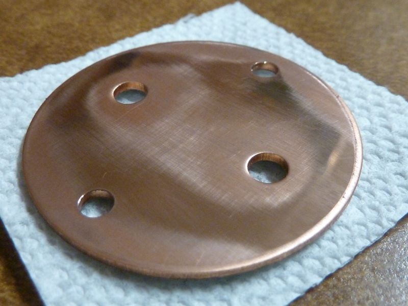
Flat surface sanding with 2000 GRIT paper shows the MCPCB is not perfectly flat on the bottom. All around the holes the surface was lower, perhaps slight deformities from the hole drilling in soft metal like copper. Usually I would drop to rougher GRIT's and get it smooth, but I figure there's enough surface area smoothed out and differences are minimal.
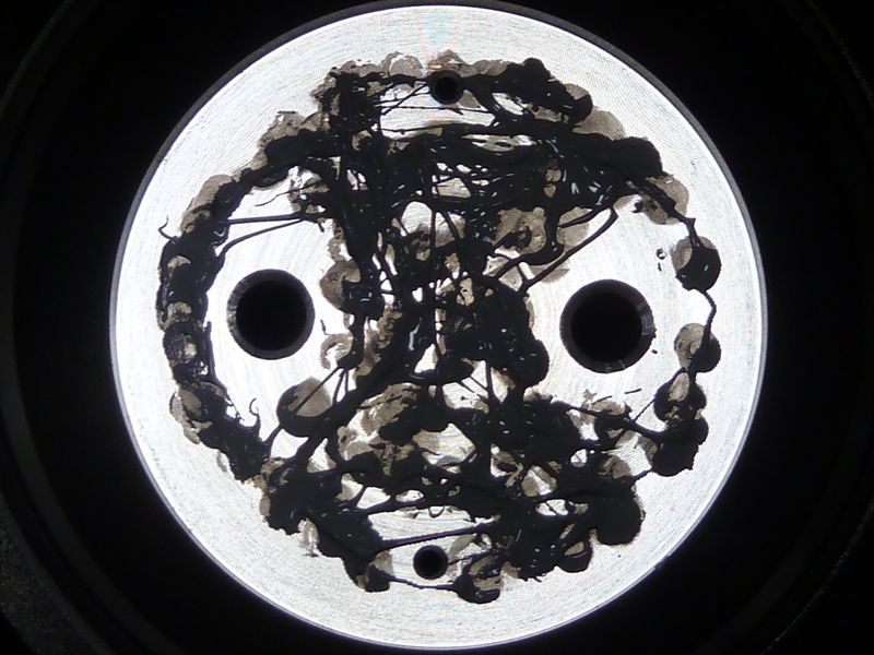
Applied healthy amount of MX4. The Stock light had maybe 60% coverage:
Fully assembled. The pre-tinned pads are done with something high temp, like lead free solder. Next one I'll be sure to remove as much solder as I can before assembly. Turned the iron up to 750F just to be able to melt it.
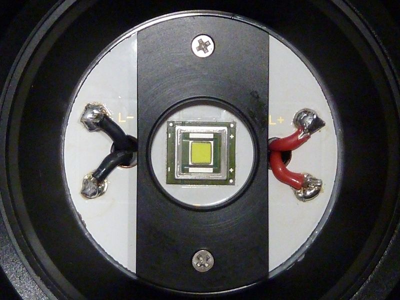
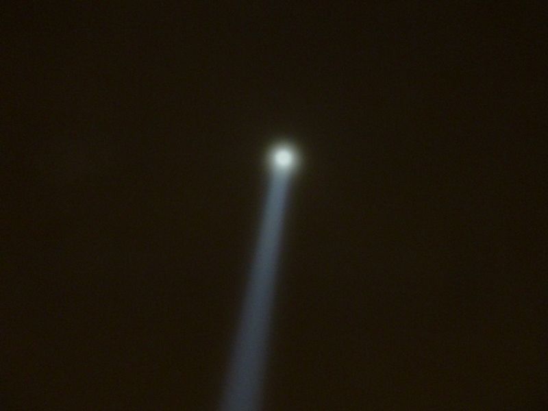
I would say the end result has the LED pretty well centered, though I'm sure not perfect. Hot spot looks very good.
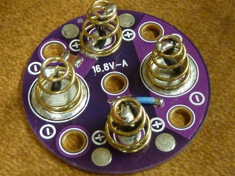
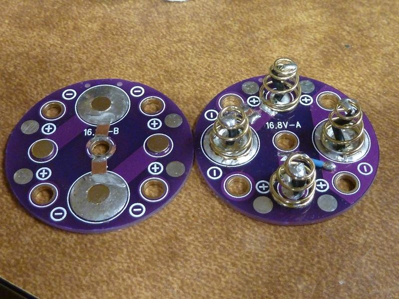
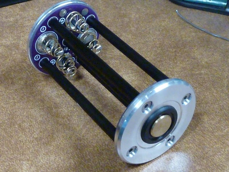
Note: the carriers in the kit had most screws untightened, and the brass contact pieces were loose as well. Easy to check and tighten. A couple of screw heads were slightly stripped but could still tighten and loosen.
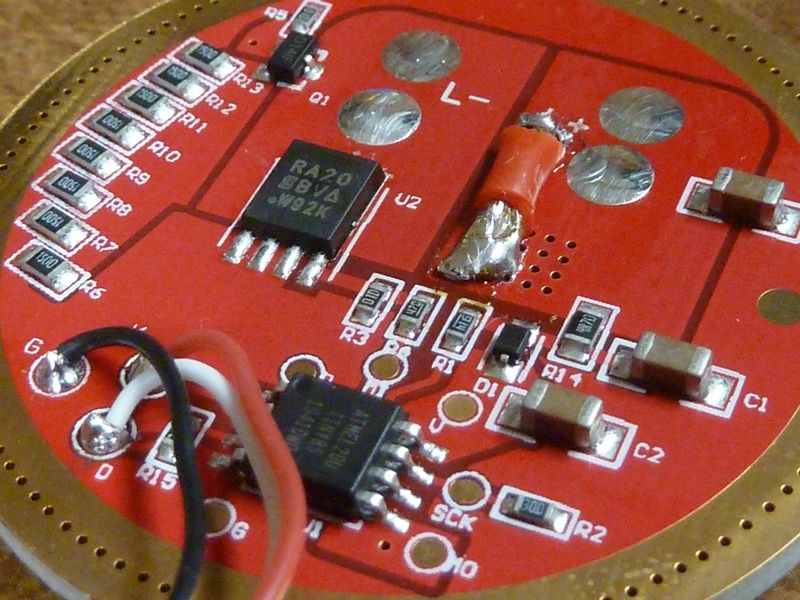
Strange that the driver seems to have contact points for flash re-programming, but they are on the inside, not the backside.