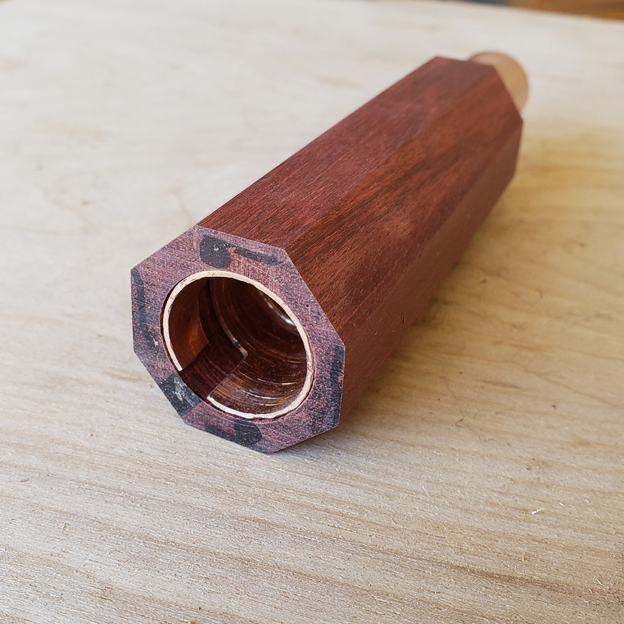
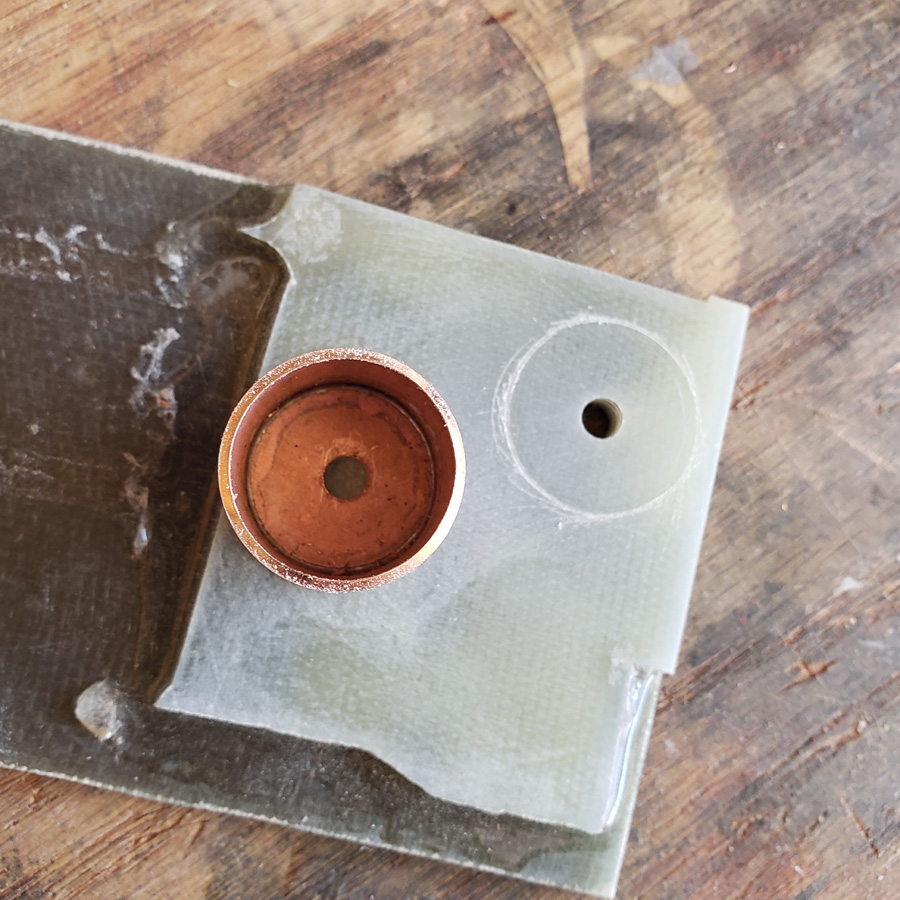
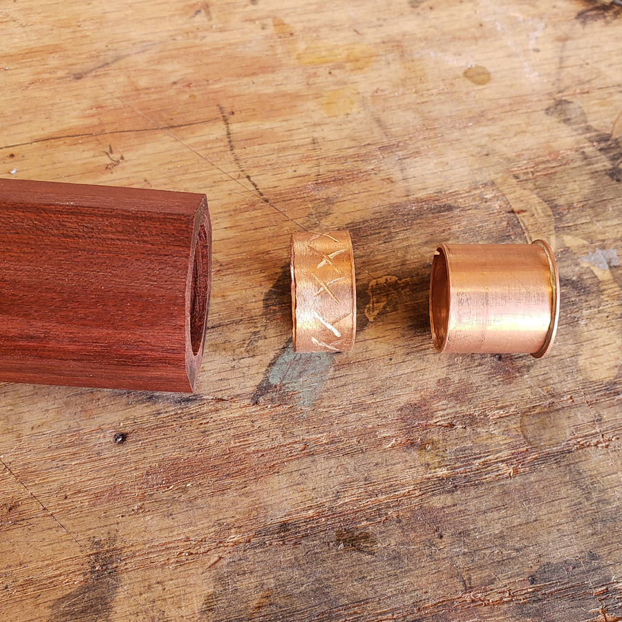
After the epoxy set hard this is what I had…
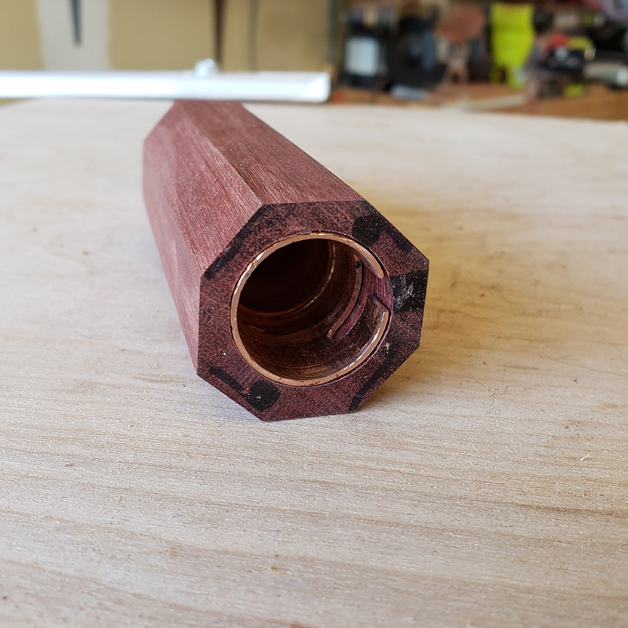
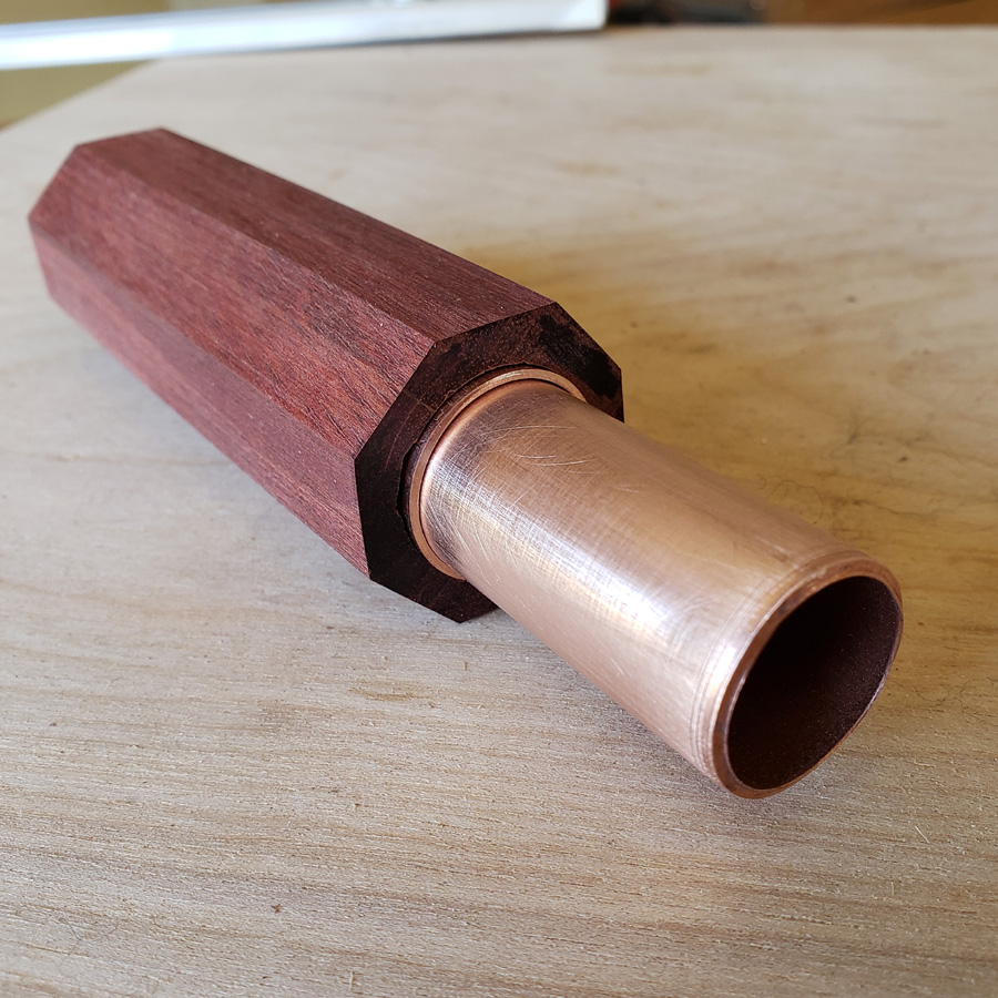
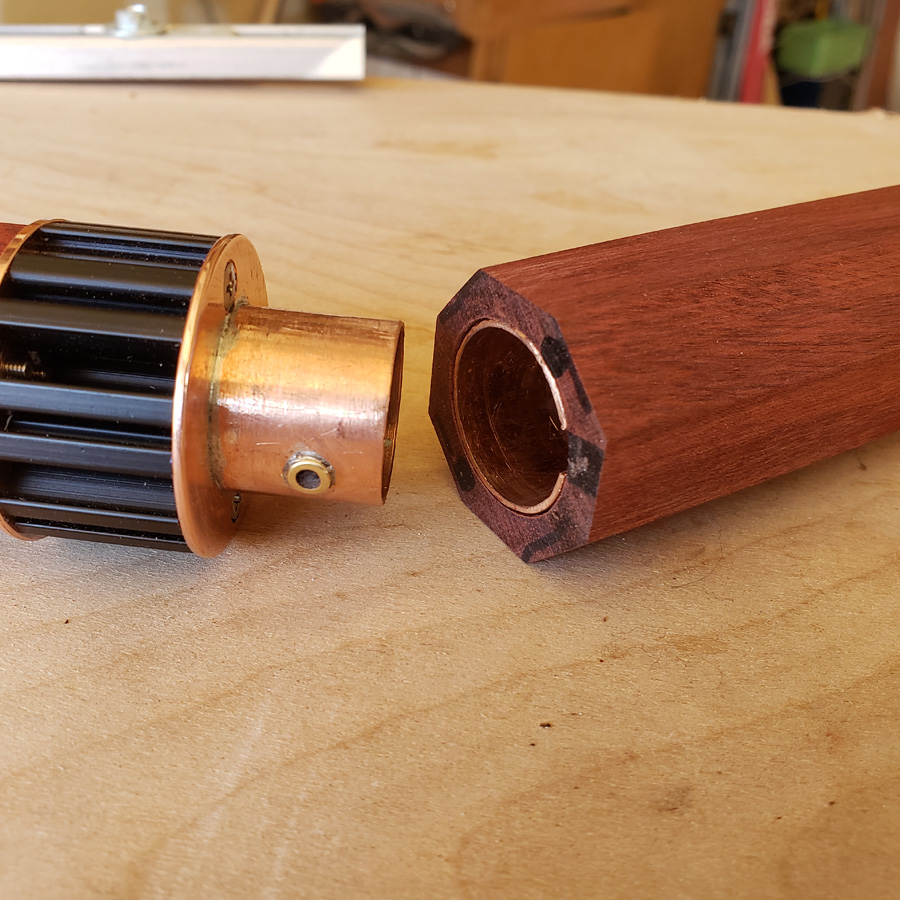
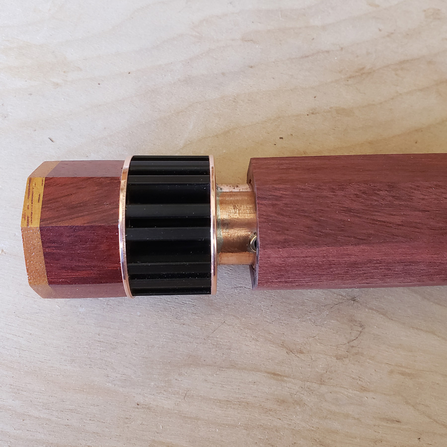
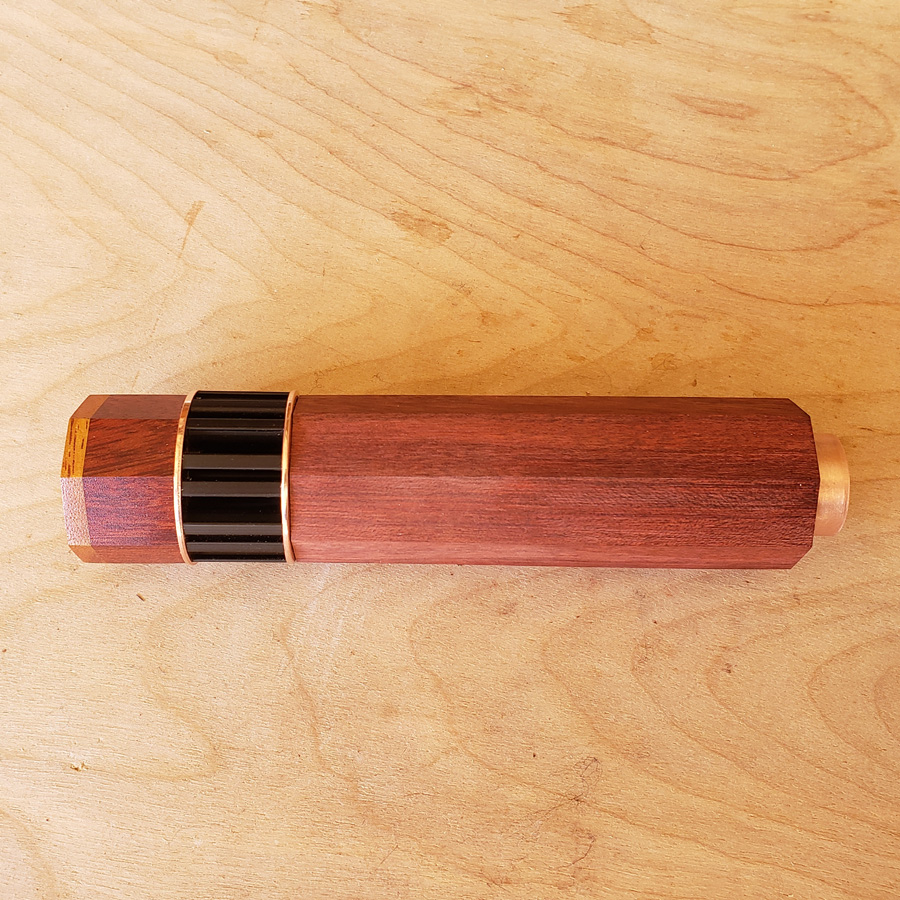
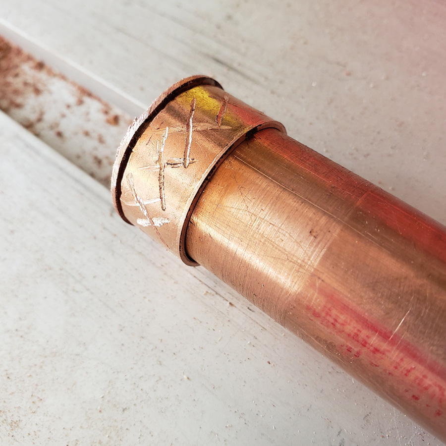
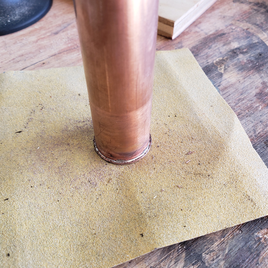
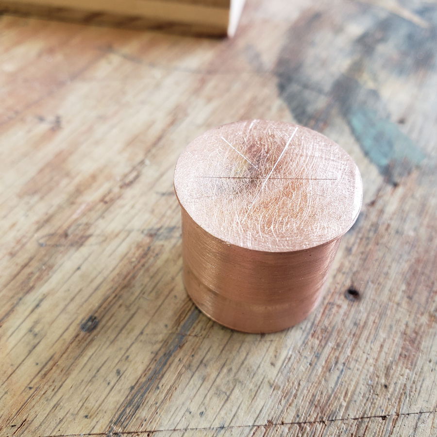
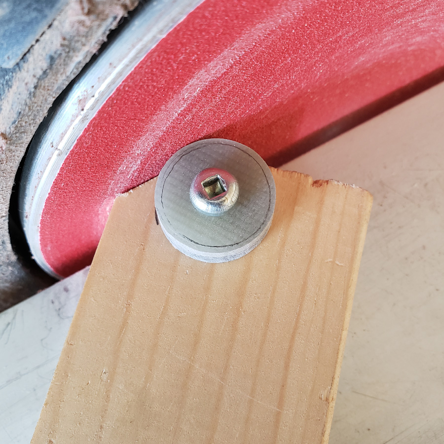
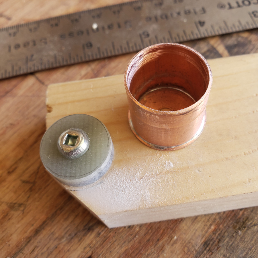
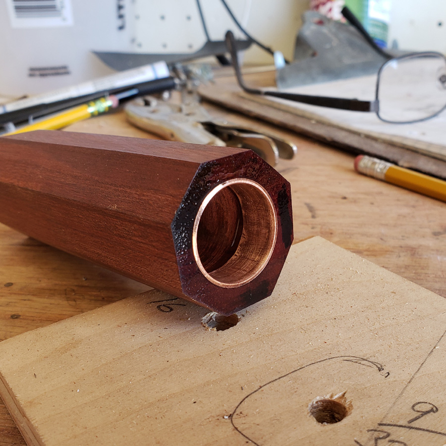
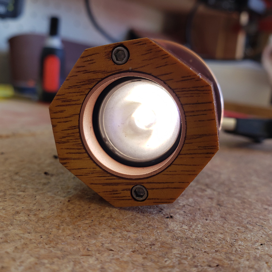
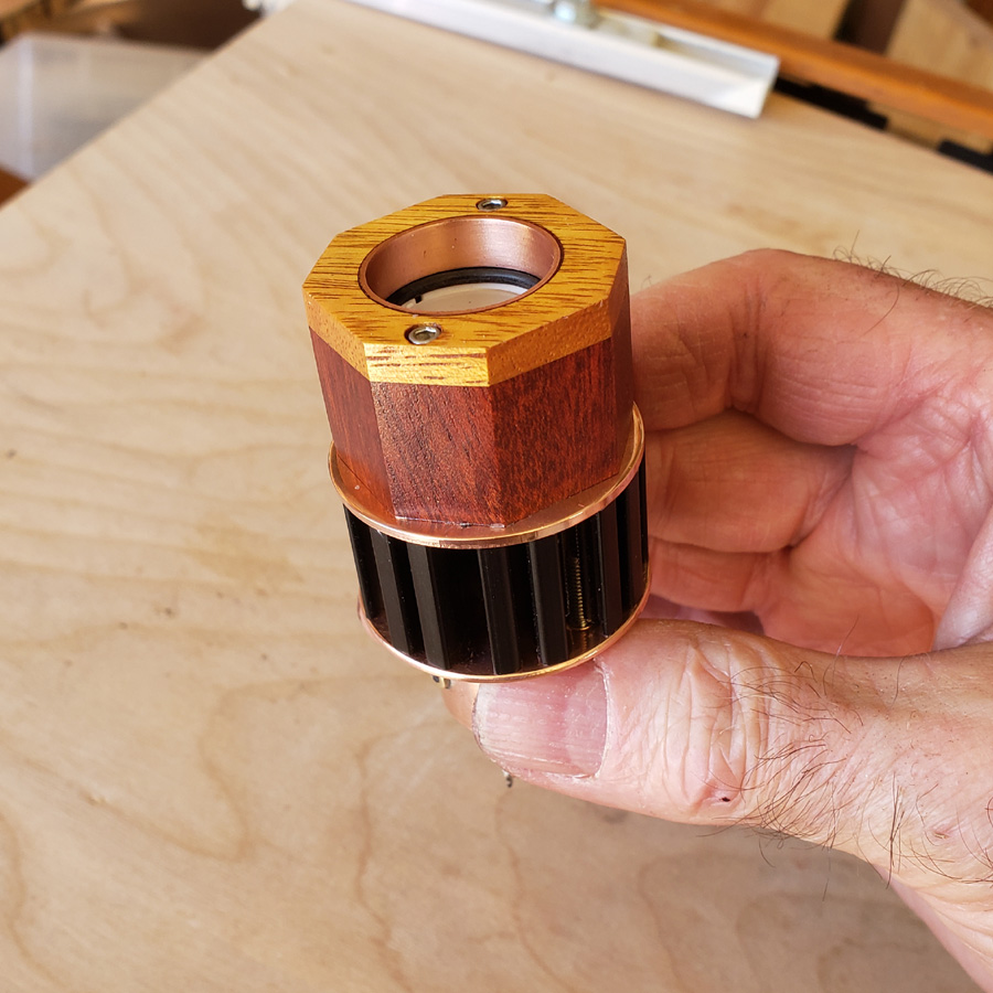
After sanding the front with the benchtop beltsander with 180 grit I sanded the front face and the 8 octagon faces manually working my way through 220, 320, 400, 600 and 800 grit sandpapers. I sanded the copper ring insert with same grits, sandpaper wrapped on a finger. Then I sprayed the head with clear satin finish lacquer.
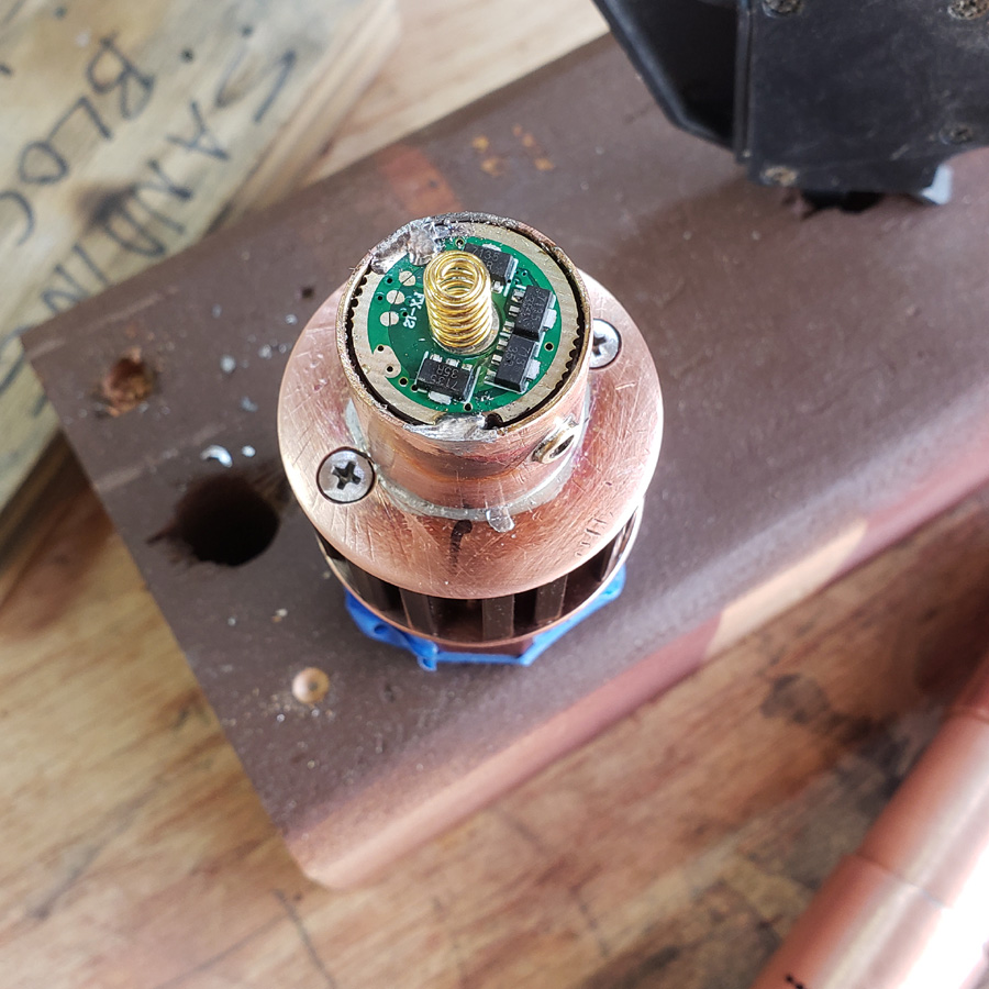
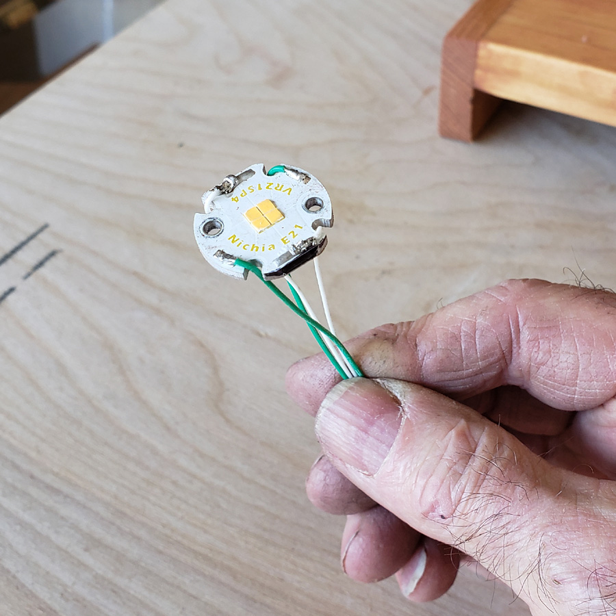
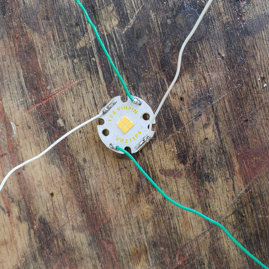
On to the mcpcb with Nichia E21A emitter, from virence.com. This mcpcb uses 4 wires to connect all four emitters to a power source/driver when all 4 emitters are used in parallel. Normally I would use some silicone insulated wires, probably 24 gauge for a light like this. However the wires have to take a course with lots of turns following channels in the heatsink. I was worried about nicking the insulation as well as the OD of the silicone wires. So I decided to use 26 gauge teflon insulated wires. They are much thinner and the insulation is very tough. It is also stiffer which is a compromise.
IF I had used the triple as I started out this wiring would have been sipler at the wires could then have a direct run down the center hole in the mcpcb and heatsink. OH well.
Green is red (+) and white is black (-).
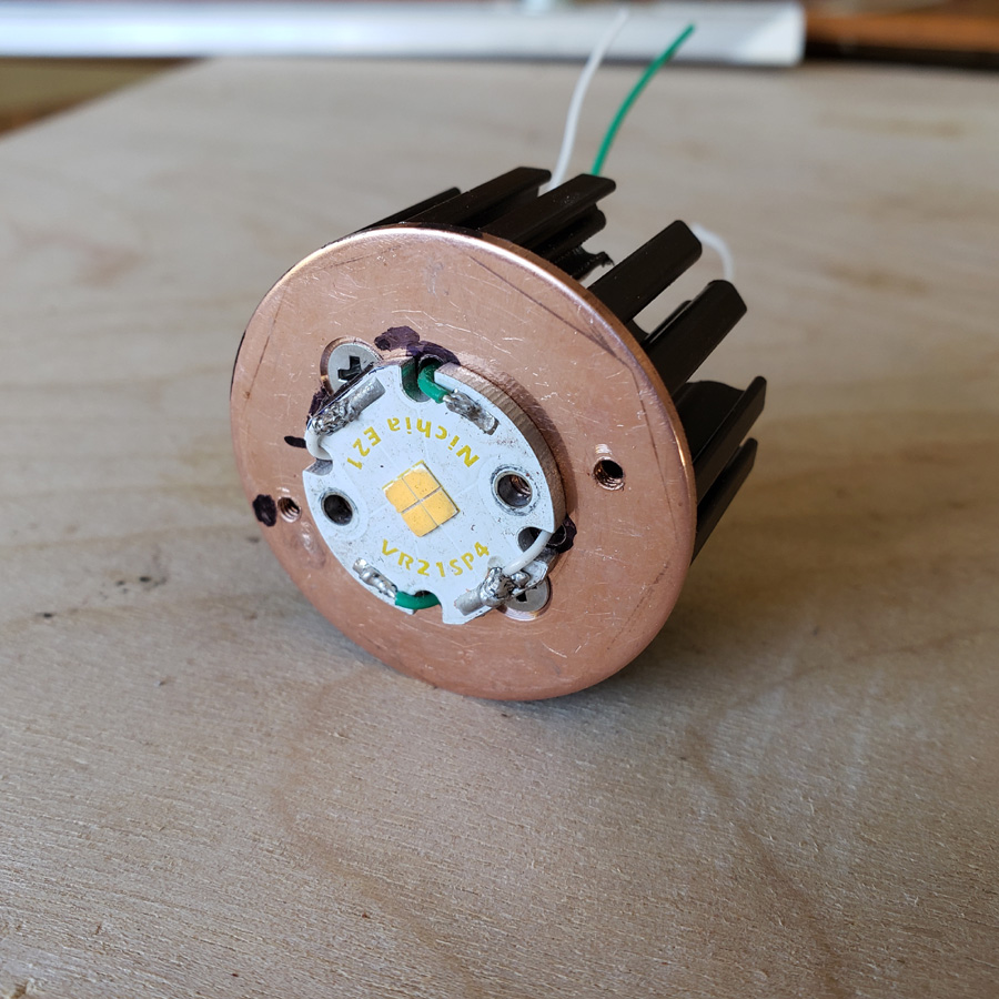
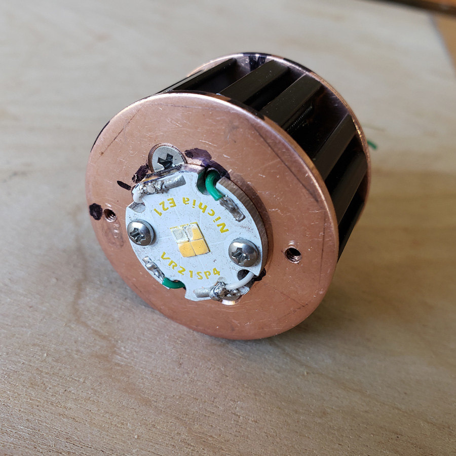
Here is the mcpcb fitted to the copper disc and that fastened to the heatsink. Each of the four wires has its own route through the mcpcb and heatsink.
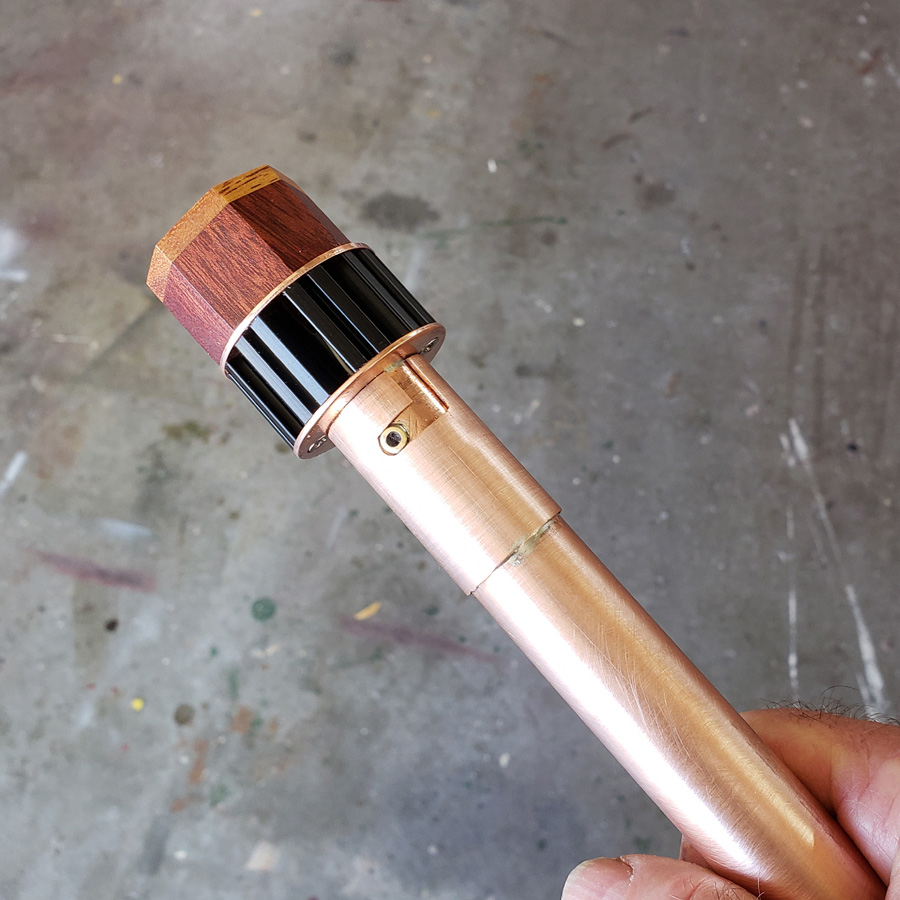
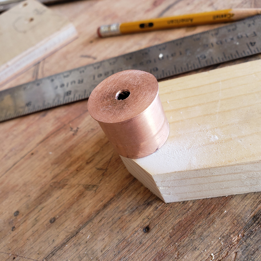
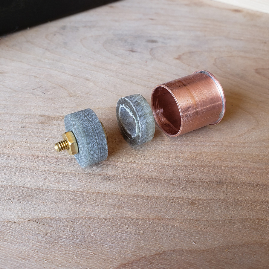
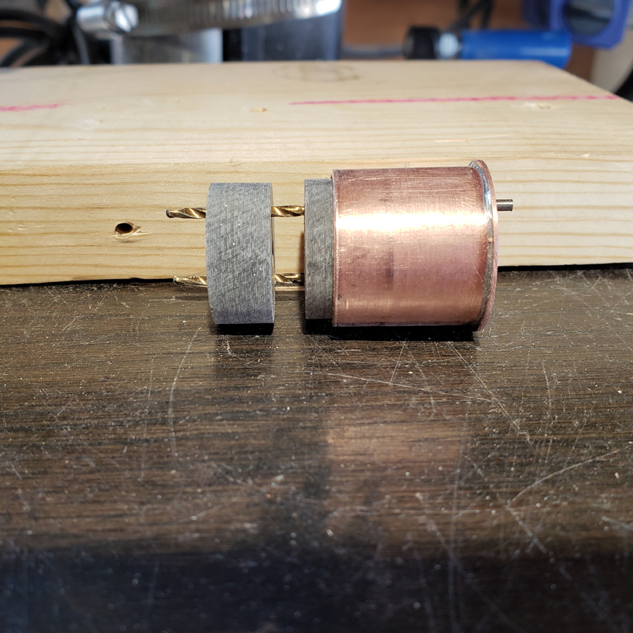
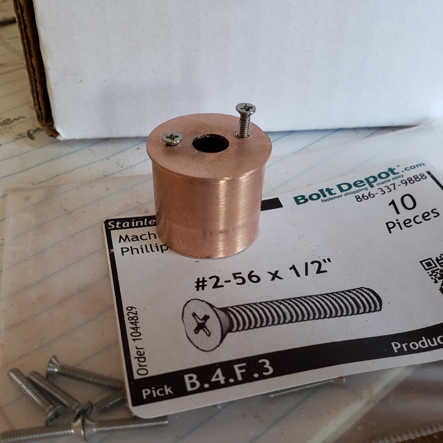
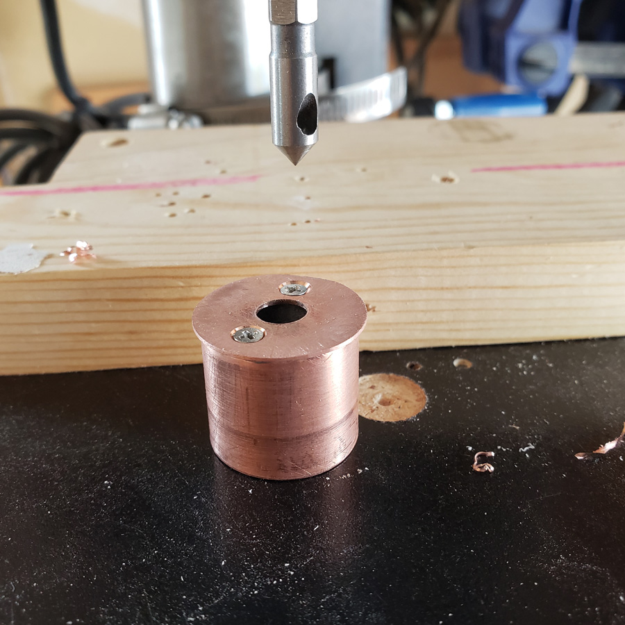
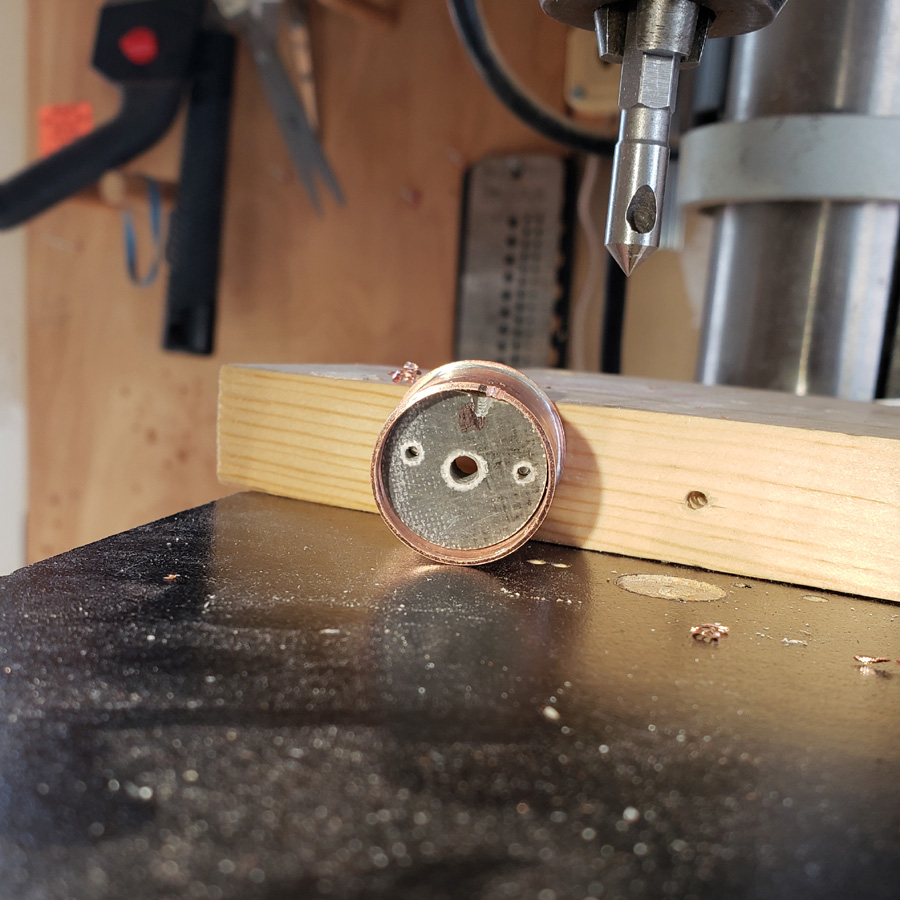
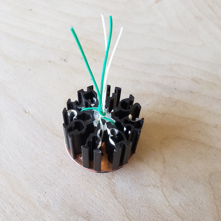
Twisted together the wires then will pass through the rear copper disc and into the copper driver mount/pill.
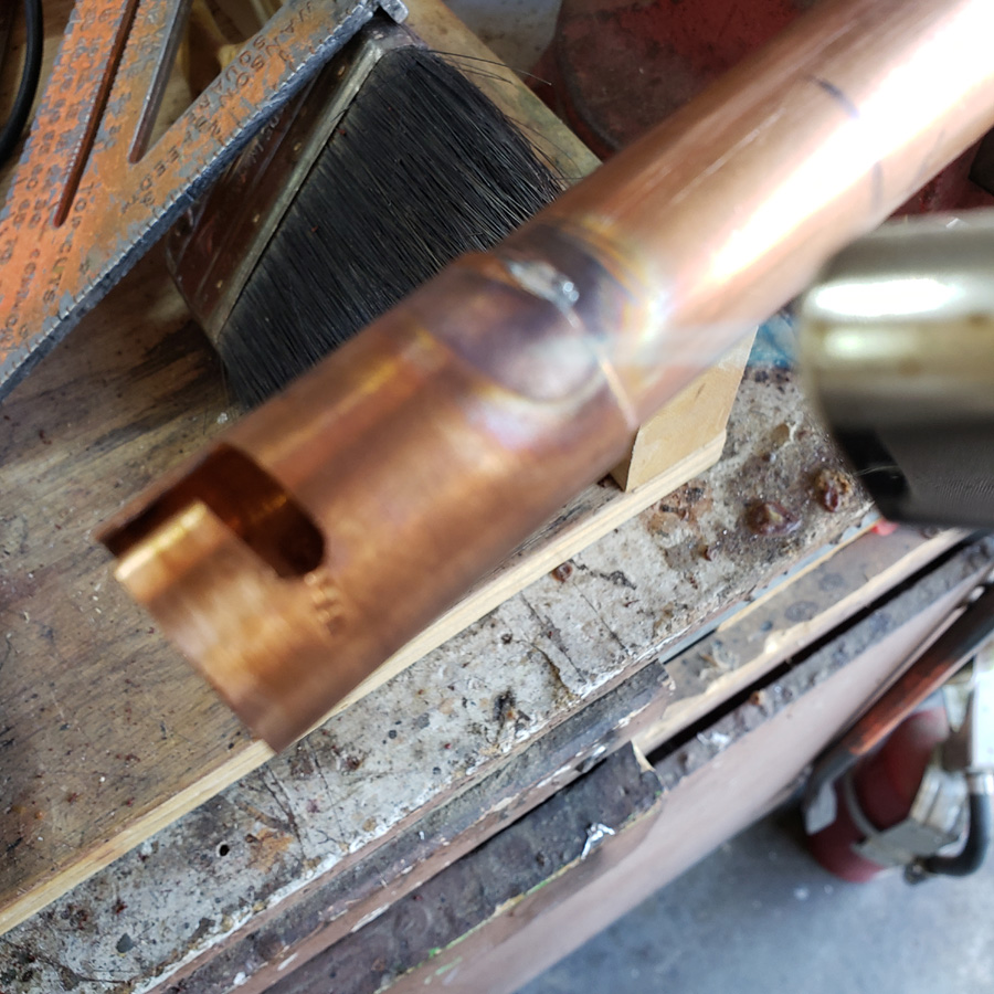
A moment of inattention brings disaster and a swear word or too!!! ![]()
![]()
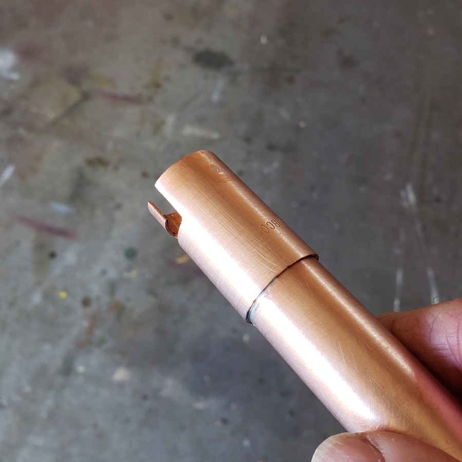
It is a good thing I got two of these mcpcb’s when I ordered from clemence. ![]()
![]() I transferred the wires to the second mcpcb.
I transferred the wires to the second mcpcb.
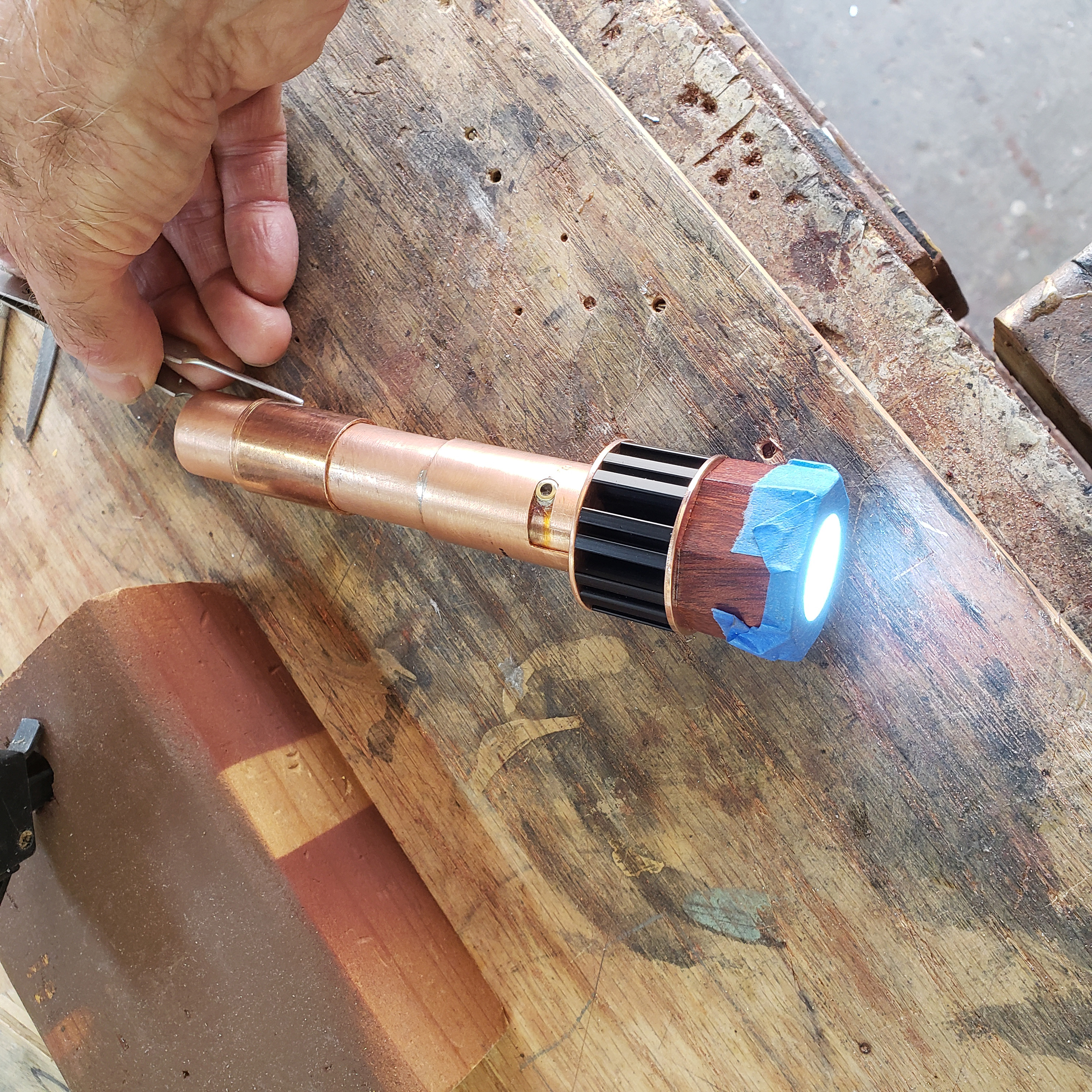
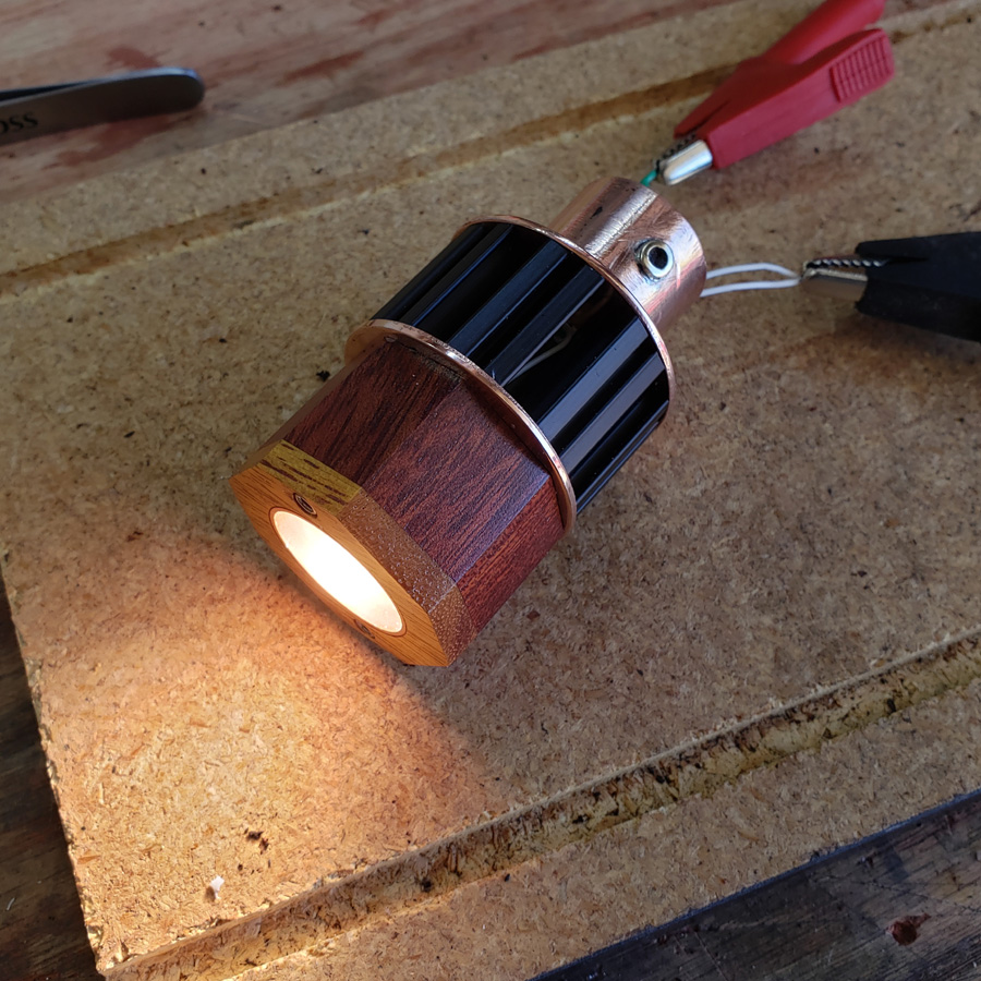
With the front end of the head assembled I connected the mcpcb to my benchtop power supply. Here it is at 2.2 or was it 2.3 volts and .20 amp.
Here it is with a little more voltage and amps…. 2.5 and .40 amps
That’s it for now. Thanks for looking.