Finished the 3rd conversion kit upgrade. This time made the following changes;
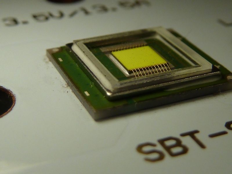
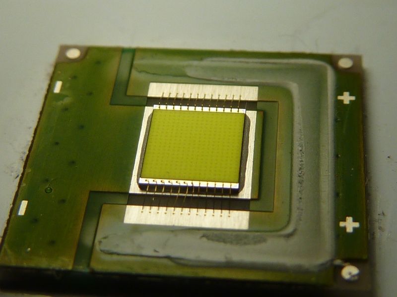
removed the window on the SBT90.2 LED
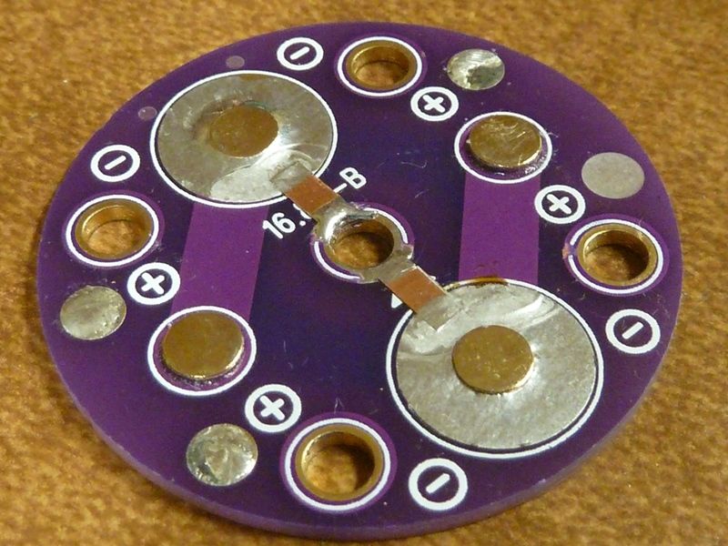
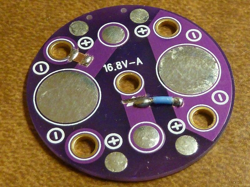
removed R1 and R2 resistors on the driver - they are not used as voltage dividers and add to parasitic drain
With the window:
Window removed:
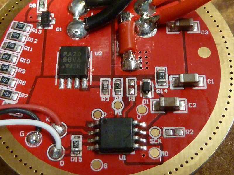
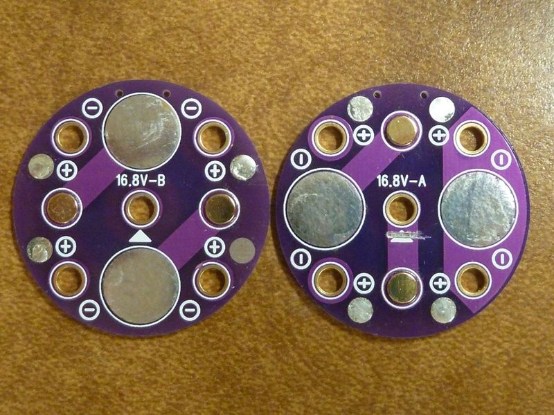
Driver changes;
swapped 20 AWG wires with 18 AEG
swapped FET from SIR800DP to SIRA20DP
swapped 10K R15 with 5.6K ohm (to make switch LED brighter)
removed R1 and R2
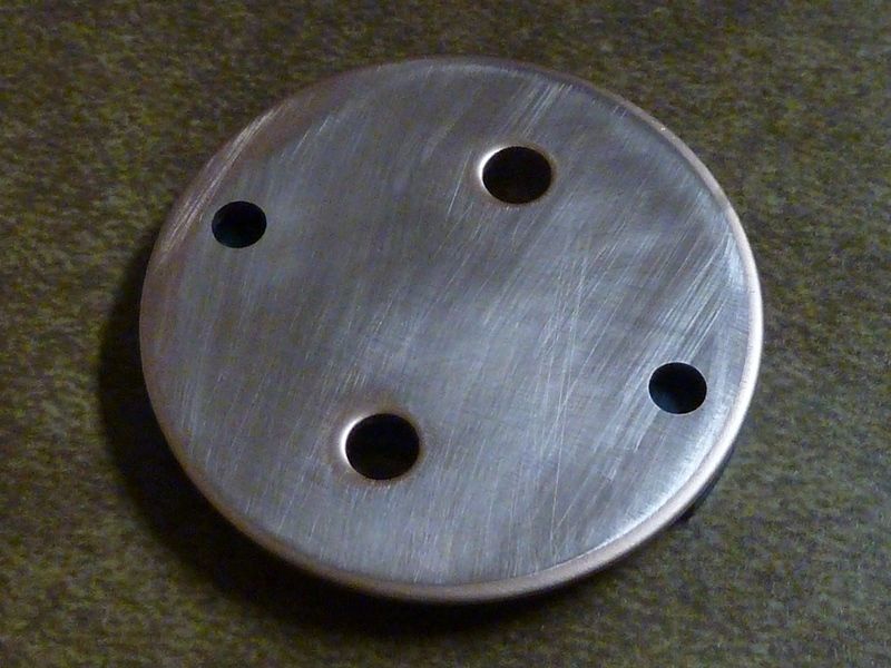
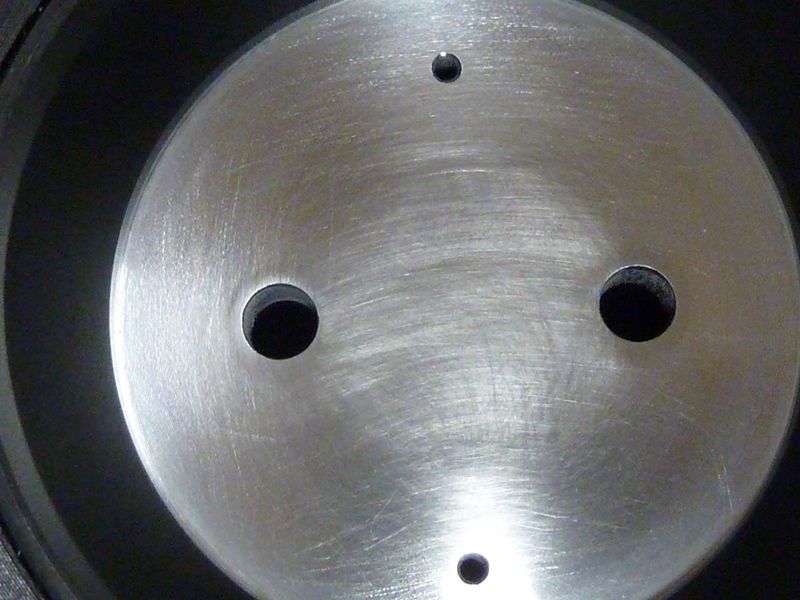
Polished MCPCB and shelf top to 2000 GRIT. Also flattened out the MCPCB with a couple taps on a large pin punch (flat end):
With this kit I measured ~2,100 kcd (~2900 meters)
I compared the 2 kit modded lights on the same set of carriers and cells, with one light having the SBT90.2 window removed, and measured about a 4.2% gain on the ilght with the window being removed -- everything else the same (driver FET, LED wires, etc.). This wasn't very scientific, limited to just one trial, and being it was done on 2 different LED's, 2 different lights, and I measured the one with the window first, and didn't recharge the cells. But still, it indicates there is probably an improvement. If I were to guess, it may be closer to 5%, maybe higher.
The switch LED did not get much brighter - hardly noticeable - not sure why it did not end up much brighter since the resistor value was nearly halved. I suspect the switch boot cover is not so transparent, not as much as a Q8 for example.
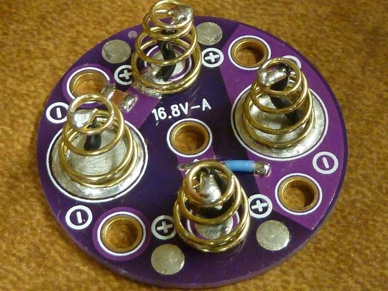
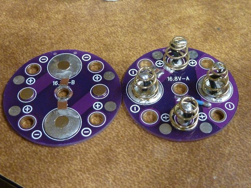
Carrier mod from 4S to 4P. I did two carriers the same way.
Decided to use old Q8 springs (large ones) since they are longer and narrower. Hot air station worked great on removing the springs and brass buttons. Used thin copper sheeting to make the low profile bridges, and 20 AWG teflon wire.
For the springs mounted over the prior button contact pads, I scraped off the traces to expose the copper in order to solder the springs down. Wherever you see soldering direct to a via, the coating was scraped off to expose the copper trace. Used 22 AWG bypasses.
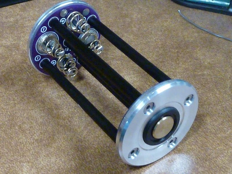
The original GT carriers can hold longer batteries than the 4P stock GT90 carriers, so a stiffer spring arrangement can be used. Since there's less spring compression, the bypasses are a better option. Thinking these should perform a little better than the stock GT90 carriers.
Did you re-flash the firmware on the driver when you removed the R1/R2?
The firmware is the same firmware as the GT70 which does use the R1/R2 arrangement as far as I know, they just adjusted the resistor values for the lower voltage.
5% gain from removing the window is what Vinh said he got as well, so sounds perfectly reasonable to me.
What do you think - would a bypass on the spring under the brass cap help much? I'm think'n it might on these modded setups. It looks like a high quality, (beryllium?) spring but it's carrying a ton of amps through it. We are probably over 25 amps and thinking the output curve on the SBT90.2 is probably flattened out anyways (djozz LED test), so probably not much of a factor.
Hhmmm... Maybe it would help to hold higher amps for longer
What's pretty cool about this FET driver setup is that we are probably pulling about 30 amps or so, think VOB measured 27 amps, but 30 amps equates to only 3.75 amps per cell.
Really 3500 mAh cells would be the best option to go with. From tests I've done with the Q8 in the past, the 35E's did pretty well. Was thinking of trying 25S's or VTC5D's but probably not much point.
I am finding measured variances on different cells. For example, I got some 30Q's from 2016 and they are showing their age. Coming off the charger, aging cells will drop fairly quickly to 4.18V/4.19V even though the charger is set to 4.22V. These cells are getting lower #'s then newer 30Q's on the GT90.
SONY cells seem to age/degrade quicker than Samsungs, at least it's been my experience with them. I've seen my VTC6's and VTC5A's and VTC5D's all degrade quicker than Samsungs.
I own over 30 lights, from mini to gt and ms18, the only light that kinda makes sense the light with a active cooling system.
I would have more lights but they are almost all the same, too damn hot and unable to sustain high outputs.
Build cooling systems for your lights instead of bypassing springs and modding to get them hotter.
The issue with cooling is that you either go with massive heatsinking like the GT4 for passive cooling and the GT4 is already at the limits of that.
Or you go with active cooling that is loud and annoying.
Active cooling can be improved but regardless of how it is done it will be really hard to make it truly weather proof over the long term since small fans simply do not play nice with real world grime/weather. It can work well in a lab environment though.
Having given a fair amount of thought to active cooling setups, there is room for improvement for sure but the cost would climb in a real hurry and the lights would loose practical uses with it due to increased size/weight along with it.
The best setup thus far I have come up with is a actively cooled design that gives up on weather proofing and simply makes the fan easy to replace when it fails. The cost for such a designs would be a lot more then existing designs to do it properly though. Like 2-3x the price.
I have one idea for a basic active cooled design that would net moderate gains but it only works with a specific flashlight setup. and would still be bulky.
Ding ding ding, Been saying this quietly for some time as I usually get heavy push back for even suggesting that the thermal path should be compromised.
I did this to an extent with my EDC and love the results.
You know, this is what they do in commercial lighting. Doing it for years with old style bulbs but betcha they are doing the same thing with LED bulbs.
Hhhmmm. deja vu - think we had this conversation before?
LOL, I actually still think that is a good option for the GT4 style light (assuming that it would be manufactured properly, which has been the issue so far, no one I trust to do it right), the GT didn’t output enough heat to make that necessary IMO.
This is a review of the Astrolux MF05 Flashlight and it is compared to the GT90.
You cannot tell the difference in the video beam shots !!
The GT90 is on the left.
.
You don’t really need to measure the LED temperature. The main reason for cooling is just so that you can hold the light without burning yourself. The actual LED can handle much more heat then your hand can. Over 200°C. The main point of cooling is just to prevent you from burning yourself.
You can get a rough idea of the wattage being put out by the LED just by calculating the voltage and amperage. I’m sure the SBT 90.2 is well over 100 Watts.
Heat sink with a large surface area like in the picture can work with a very small point source of heat if you use a good spreader such as an intermediary copperplate. Copper tends to spread the heat out very evenly.
Note, I’m not sure I interpreted what you asked correctly.
The reason for thermal stepdowns and cooling is not about user comfort. It’s about not burning the user and getting sued.
There is nothing baffling about flashlights being round and no active cooling. The explanation is super simple. The round shape is dictated by the reflector. It doesn’t make much sense to machine a square flashlights and put a round reflector in it. Square is harder to machine and has extra weight compared to a round flashlight.
Adding active cooling tends to double or triple the cost of the flashlight and reduces the reliability. It also tends to compromise it’s water resistance. This is why you very rarely see it. Nobody wants to pay the price premium for it.