This morning I made the trigger using the leftover brass strip from the hoop. 
I bent the two pieces by placing them over the open jaws of the vise and pressing down with the handle of a chisel then bending the ends a bit further in the slack jaws of the vise. Here it is after soldering the two together.
After I had drilled and countersunk for a #4 screw I put some masking tape on it and drew the outline I wanted. After about 15 minutes with the dremel and an hour of sanding I ended up with this.
The smaller hole below the switch is for the trigger guard which I also reworked a bit.
It’s Sunday and back to the salt mines tomorrow so that’s it for a few days. I have a few internal things worked out as well as an idea on the upper tail cap so check back in on Wednesday.
6/27
Finally got home last night and immediately kecked up the switch button and lost about 4 hours between trying to fix it and making a new one. Oh well. The new one is fitted to the trigger and installed with the switch(pretested) epoxied into the handle. A green laser and a different reflector supposedly came in the mail today so now I get to figure out a whole new layer of “who’s idea was this?”. The good news is that my scintillatingly effervescent noggin has percolated solutions to most of the remaining difficulties. Whether I remember them when I sober up or they actually work still remains to be seen. This weekend and next week should reveal a good chunk of these parts. That is, if I can post them. SB must be having fits with all the server issues. No problem for me, I either work on the mod or hallucinate think about it.
.p. Until next time…
6/29
Another fistful of parts
Square plate becomes round with two of the small brass cylinders.
Then add the copper cap and the third brass bit.
The center piece is a 5.5 mm barrel jack, center positive. The pcb will be used as an insulator between the center post and the case of the jack with the spring soldered to it and contact established with the male brass threads that are glued into and isolated from the copper cap.
It’s 92F inside the house and I just found out the AC is dead. No more modding for now.
11 o’clock and all’s well. Down to 80F inside.
To center the male brass threads in the cap(very loose by design) I dremeled the female threads to fit snugly (actually also loose but added layers of tap to center that part) in the other half of the joint and partially filled the cap with JB Weld, plopped in the male threads and twisted the joint together making sure the cap and tube stayed aligned. When the JB set, I unthreaded the two halves and filled the cap the rest of the way, topping it off with the pcb, now thinner, notched for a wire, and stripped of all but the center contact disc. When this sets I’ll solder the wire(already soldered on the other end to the brass) and the spring and this piece will be done!
6/30
A few things got pulled together today. Both tailcaps are done (minus polish work) and the mechanical guts of the handle are done too. Layers upon layers, this needed to be done before that yada yada. Anyway, with the switch installed I made up the positive contact and installed it. And with that part installed, I epoxied the hoop(remember that piece?) and with that cured I could finally drill and tap the butt plate screws. And now for some pics.
The upper tube tail cap.
The positive contact plate for the handle. The piece of threaded plastic pipe had some plastic bag taped over one end and some JB spooned in. When cured the JB doesn’t stick to the bag and can be filed smooth and drilled. More JB to stick it together and fix it in the handle.
Ugly and going to get worse, I know. You can see the upper end of the hoop in that pic. This end gets drilled and tapped for the screw that will hold the upper tube in place. The other end is where I worked next. Drilling countersinking and tapping the two 4-40 brass screws that hold the butt plate on.
It fits!
The other thing I worked on while the epoxy set up was the laser dohicky. I pulled the momentary switch, jumpered the contacts, and hooked up a 5.5mm barrel jack with new silicon wires. (recognize them Dale? Thanks).
Right now it is inside an assortment of brass tubes that are holding the jack centered while some Fujik cures. At the right and bottom right you can see the tube and new cap that will sleeve the laser.
The trigger and guard will be two of the last pieces to be installed but other than that the handle is pretty much done save the wiring. Most of the remaining work is up top. How exciting!
7/4
Happy independence day! :party:
Laser mounts done.
And started working on the fins to body connection.
The MOSFET chips came from Mouser yesterday so I’ll have to see if I can swing that touch switch. Crashing now, bye.
Teaser pic. Soldered the trigger guard in(upper joint only, handle end gets screw?, epoxy?). Tape on reflector to keep metal bits out.

Off to the parents for the fourth. Dad just called. Mom in ER with Afib again.
7/07
Mom’s better now and I’m back home for more modding. This time around I installed the jack for the laser plug in the larger rear mount that now has a hole following each of the two mounting tubes. The one in back gets the wires and the one in front is drilled all the way through the top to allow me to get a screwdriver to the top handle screw. Complicating things I didn’t make the rear tube deep enough for the jack to sit behind the hole. The radio shack jack is much bigger than the one I used in the tail cap. I need to get this part down under 14mm in length to clear the hole so I started hacking away at it. At 17.5mm it fell apart. 
Undaunted, I discarded the case and collected the useable and necessary inner parts and proceeded to make my own case.
Silly me, I should have been daunted. It worked, but I had to spend half the night getting it to fit and adding wires(ended up with the biggest tip on the iron at 450C) to get the metal base plate of the neg contact to solder to the tube then epoxy the pos contact back in place. The other half of the night was spent getting the jack installed. It to two tries to get epoxy in place and the jack held centered without having the jig end up a permanent part of the light. Lots of futility, cursing, wasted devcon and panic but the Drake family motto”Perseverando” kept me going until I had this. 
If there doesn’t appear to be a logical order to the build or I seem to jump around its because there isn’t and I do. Some parts get held up while I figure out how to do others, and some, like the MOSFET switch alter what I might do and hold up steps I already have figured out. Almost all of this project has been that way. Only one more week of updates, though. I’m going to miss this contest like a toothache. :weary: Just kidding, the fact that this is a contest is a big part of what has kept me going on this.
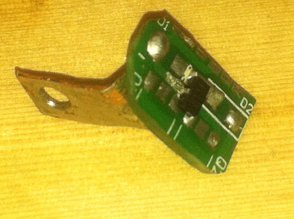
Having run the wires for the laser I could finally set the female threads for the tail cap. This brass part has a wire soldered to it and carries the positive from both the battery and charging jack. It’s isolated from the copper outer tube by layers of JB weld and a fiber washer. Since the touch switch worked I made up a pcb from an old 4x 7135 driver board with a copper strip soldered to the back that is screw to the brass hoop with a 4-40 brass screw. The resistors have since been added.
The big item on today’s list was the bezel. I cut it from an old salvaged brass threshold about 3/32” thick.
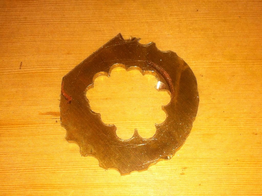
I cut two strips of .010 brass sheet and soldered them into a round hoop.
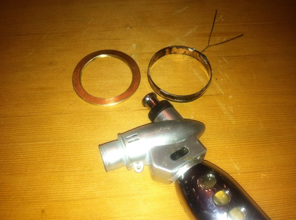
After cleaning it up and sanding the edges flat I tinned one edge, set it in the solid front piece and reflowed them together.
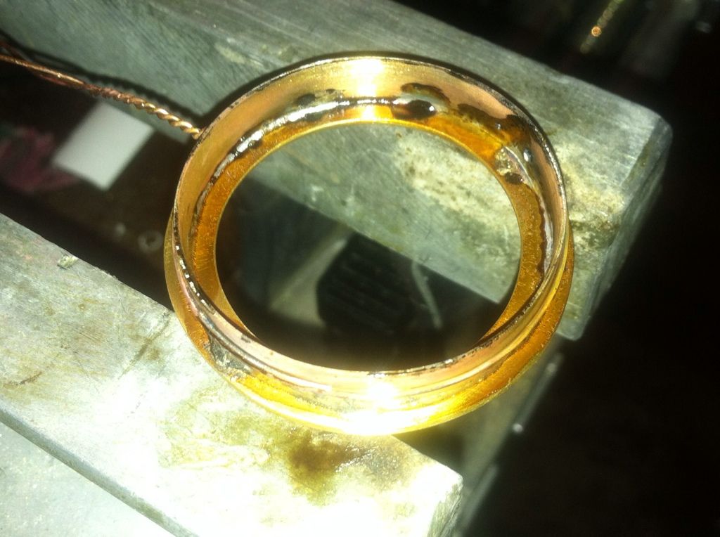
Cleaned this up again and ground/filed/sanded the edges down.
Stay tuned!
7/11
The next two days are make or break for me as I have to work this weekend and won’t have time for modding so here we go.
Originally I had toyed with the idea of adding wood to the grip but nixed that as its already been done and opted for leather instead. I have a wallet that while still almost new started one of the seems so rather than trust it with ID and cards it will get a much more favorable (hopefully) use here.
I spent the last couple of days gathering my courage, cutting leather to shape, and scraping the edges thin in preparation. What I know about leather wouldn’t fill the thimble I picked up to do this but the handle needs something more. I used double sided tape for golf grips and padded/shaped the rear edge of the grip with a few extra layers of leather. The narrow strip goes under the stiching to hide any brass that might show.

Here it is partway stitched up(it gets the last stitches at final assembly). I drilled two holes through the leather and brass for the touch pad contacts then widened the holes in the brass to ensure isolation.
These are the two touch pad contacts along with the MOSFET circuit. The brass rod is 3/32” Dia and is drilled through the copper before soldering, then dremeled down to size and cut off. 
And here they are in place. Just slide your thumb over these points and laser is on. (knock, knock).
Tomorrow will see more work on the upper tube pieces. Good night.
7/13
The good news is I got the too half assembled and fired it up and it works great. The bad news is the laser seems to be toast. A bummer but what can you expect for less than $10. 
I hope the lack of the laser doesn’t DQ the light but it’s certainly a step back. In any case, the laser is modular to the light and won’t keep me from finishing the assembly.
7/14
I seem to have forgotten all I have learned about making a pill. I toasted 2-105C drivers before deciding to remake the pill into something workable. I made the new one I two parts to ease the soldering on the ground and added a small wire to make that connection. The two parts press fit together after attaching the driver.
The part with the wire is the pill for the driver, the other is the first section of the sink for the led. That gets more layers and longer to the point that the driver pill fits entirely inside with only the contact plate exposed.
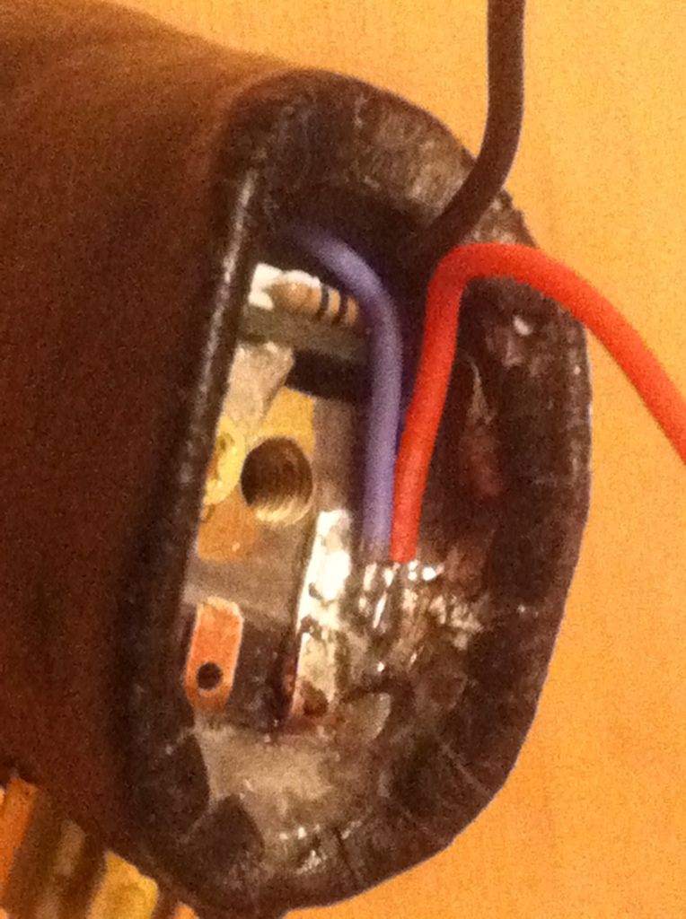
Even though the laser had died, I installed the MOSFET switch in the handle. You can easily see the 1 meg R and just barely make out the lead of the 1k R by the red wire the rest of the board is hidden. I made a contact plate for the positive connections on one side of the switch and jumpered one of the brass touch contacts to this.
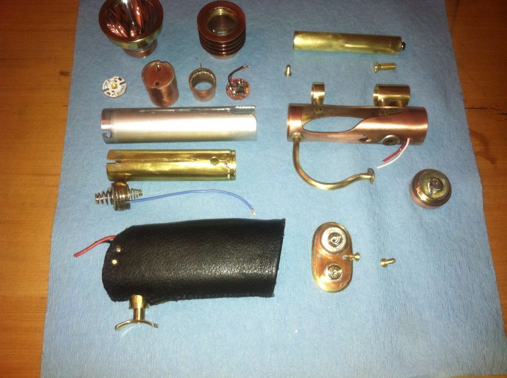
This is what the light looked like at about 3am this morning. I finally had all the pieces done but still needed to put it all together. Even here, I had to modify some of the parts to get it all put together.
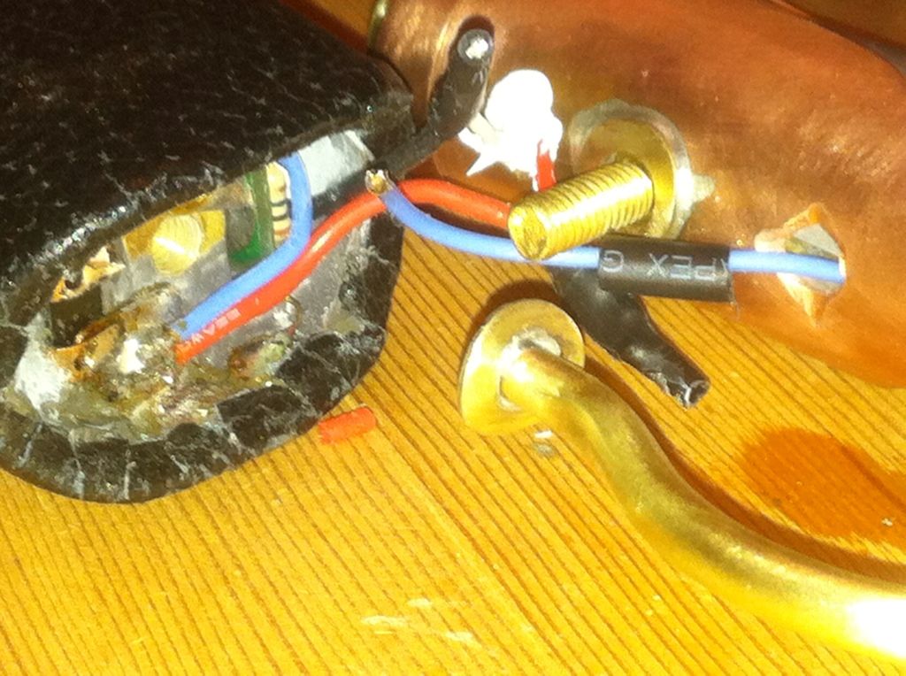
The most anxious point in the whole project was attaching the top to the handle with all the wires hooked up. I’d done it numerous times dry fitting without the wiring but keeping the wires short made them stiff and hard to settle in place.
The last thing was threading the screw that holds it together. The screwdriver goes through the forward tube of the rear laser mount and into the screw. Had to be sure not to pinch any wires now!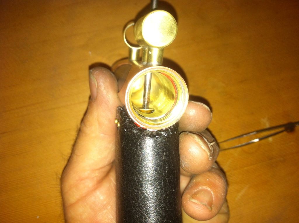
Thanks for sharing this build with me. I hope it helps you with your next project. I learned a bit. I hope I remember some of it.