Yes and yes. https://budgetlightforum.com/t/-/18955#comment-411218
Ah, never knew that the two wires are parallel, thought that current was going from one to the other, that explaines easy why they both go.
Perhaps an idea is to start with a functioning led and 'enforce' the bond wires with solder blobs.
Hot air would work better, probably from underneath to keep from knocking anything out of place. If you could take a suitably small piece of wire formed to mirror the bond wires, give a light coat of paste, get it positioned and then add heat...
Can you show a pic with your resistor mod?
Did you use a Trim-pot?
djozz sorry about the OT.
Added one R120 for about 4,7.
Two R120 in series (on top of the stock resistor) was about 3,65 I think. Stock output on mine was quite close to 2,8 I think…
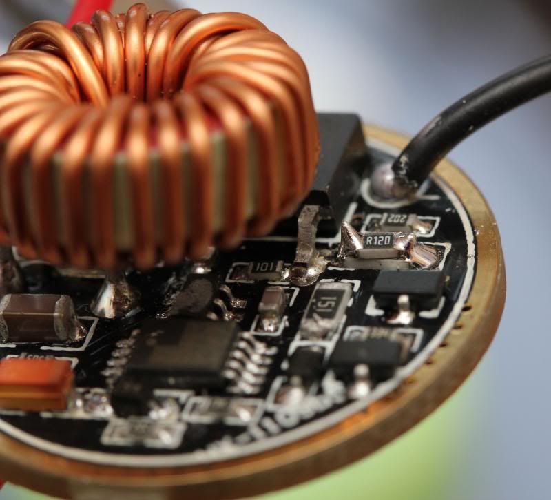
Its basically the same driver that I modded in this messy thread. But there are a few differences. If you have the same looking driver, yours might have differences too. I have not tested it for more than a short period though, so mod at your own risk… ![]()
Edit: I have no intention of using the huge stock aluminium mcpcb in that light. Ill kinda make a cooper “pill” for a copper mcpcb to sit on… Ill might make a mod thread some time in the future…
I'm seeing consistent issues with not being able to get 3.5A+ out of an XP-G2/SinkPAD combo, whenre I can with an XM-L2, in a single cell Nanjg driver. I think you're right - XP-G2's have a higher Vf demand.
What is the amp tailcap measurement? I've been unable to get above 3.3-3.4A I believe. It still does well and bright, but just not getting the full amps.
Basically the same as with me and others… XP-G2 seem to need two cells (and a buck driver) in order to go higher…
That's perfectly alright, I am guilty of that myself all the time.
fair play for trying ![]() I’d suggest some enameled copper wire to replace the bond wires, but making suggestions is easy when you’re not doing the work!
I’d suggest some enameled copper wire to replace the bond wires, but making suggestions is easy when you’re not doing the work!
I wonder if dedoming with gasoline weakens the wires. I know gasoline weakens some metals. I learned the hard way when I soaked a motorcycle chain in gasoline to clean it.
Or maybe the dome just physically supports the wire and helps prevent it from sagging and shorting at a lower amperage.
I have tried once to repair a bond wire on a XML and the results were like yours…one drop solder on the phosphor and the wires still not connected…
There are conductive epoxies that are advertised as a replacement for solder. No idea how they’d do in a high-current, high-temperature application. But it’s possible something like that might work better at repairing bondwires if you can find one with the right specs.
MT-G2 is 1.5C/W which is pretty low, Luxeon T is 3C/W.
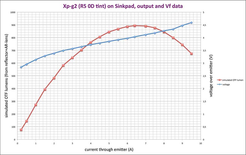
I took some time to put the video data into graphs, and in these graphs the numbers sure look official  , watch out for good-looking graphs!!! In each video I turned the current up to a fairly high level and then turned the current down to minimal and started over again but now until *poof*, I did this to see if any 'burn-in' effect (lowering of the Vf at the same current) could be detected. It turned out that the second run both with the XP-G2 and the XM-L2 gave almost exactly the same numbers, so no burn-in effect here (Perhaps a burn-in effect will take place when the led is driven way over its maximum output).
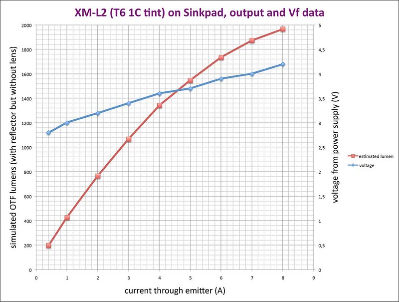
Take notice that the output lumen estimates were calculated from ceiling bounce numbers that are derived a bit different with the two leds, the XM-L2 had a big 49mm reflector on top without lens, the XP-G2 had a small 20mm reflector on top with a AR-lens. The reflector size should not make a difference for the lux-reading, but the lens does a bit. (sorry I messed that up a bit in the experiment)
I believe that the voltage reading coming from the power supply in the XM-L2 graph -although a bit rough- does reasonably represent the actual Vf of the emitter at that current. The voltage in the XP-G2 graph was measured more accurately and directly at the (thick) led wires.
I just used the current reading of the power supply for the graphs, I did not check that with a DMM (should have done that). But for now I see no reason to distrust the current numbers.
Here we go:
Do you think you could do that with a Gen 1 XML? I’d donate one if needed. I am curious how an XML U3 scales, and if it can take more current at the top end.
And thanks for taking the time to do this!
That would be interesting, and I could do that, and I do have one spare (albeith a T6), but what I lack most is time for the hobby. And to be honest: these kind of tests should be done a bit less leisurely than I do them, I am not a that accurate kind of person I'm afraid. I am hoping for someone else with time, equipment (calibrated stuff, integrating sphere) and precision to do this kind of testing (texaspyro for instance is much better equipped than me in doing these kind of tests  ).
).
Pretty clear from the graphs the Vf tracks higher for the XP-G2 across the spectrum of amps -- wish I knew this sooner, but this sure does explain a lot.
Thanks djozz!! Great work/info!!
Dedomed XPG2 R5 3D/Sinkpad/big CPU heatsink, 1-2-3-4 cells in parallel, direct drive
Samsung INR-15Q, unprotected
1cell - 2.56a 3.61v
2cell - 2.93a 3.75v
3cell - 3.15a 3.81v
4cell - 3.24a 3.85v
Panasonic NCR 2900mAh, unprotected
1 - 2.53a 3.59v
2 - 3.07a 3.77v
3 - 3.28a 3.85v
4 - 3.42a 3.89v
Wow, that's interesting #'s. I got the 15M's and 20Q's, and the 20Q's are very good - seem identical to the 20R's, but to see them beat out by standard Pana's with qty 2 or higher in parallel, is kind of mind blowing -- not sure why? Do you know?
Also, the 2.56A for a single 15Q seems rather low - I'm definitely getting higher #'s with a Nanjg driver and 22 gauge wires with a 20Q. Mine are tailcap measurements though...