Thanks for the graph djozz. With all this work you have done how and what would you use for maximum realistic performance in a largish flashlight, driver and pill wise?
I am still not very good in driver electronics (only a general idea of what is going on), so no ideas about which one to use, but I do have idea's of how I think the MT-G2 could be driven well.
I will give a general idea of how I ideally use this kind of data to make my idea of a good useful flashlight, and I guess that is not so far from how some others in this forum think. (My game is usually not about setting records while being totally inefficient and burning through batteries in 5 minutes, that's another fun sport).
Using the MT-G2 most factory lights go up to 5 amps, even the ones that use copper boards (Eagletac). That is a good idea, great output and good for efficiency and gives a managable amount of heat. But in this forum we want a bit more and we are not afraid to get our hands warmed up. Maximum output is reached at 11 amps, but the light will be hugely inefficient at that current, a real waste of energy and probably not good for the lifetime of the emitter. My personal rule of thumb with copper mounted leds is to aim at about 3/4 of maximum output: the led is used very well, the visual difference with max is negligable and it almost halves the current neccesary for the maximum output (the performance graphs of all other emitters have a similar profile so this is valid for all emitters). For the MT-G2 on copper and maximum heatsinked 3/4 of max is reached between 6 and 7 amps, so that would be my ideal. In a flashlight build heatsinking will be worse, but I'd still go for the 6/7 amps  . The led alone will produce -apart from emitted light- about 30W of heat at that current, so the build needs a good thermal path and sufficient surface area on the outside of the light.
One remark about why it is great to use these copper boards as opposed to traditional boards in flashlights: because the heat can get away from the led so easily, the temperature difference between led and body is less (I believe it is even much less), so the body can be allowed to get hotter while the led is still performing well. This is advantageous in two ways that help each other: 1) obviously you are allowed to make more heat (the led can be driven harder), and 2) the difference between flashlight body temperature and ambient temperature will be larger so a same amount of energy can be dissipated with less body surface. In practice: I have not tested it yet, but my guess is that when a copper board is well mounted with a good heat path to the body, you can continuously keep running a flashlight that is too hot to touch. One design consequence is that the battery compartment will have to be thermally more isolated from the head of the light than usual (i.e. further away).
Sorry, this is a bit of a long answer, and it is perhaps not even an answer to your question  .
.
Thanks for the graph!
May I suggest that once this/these threads get less popular. Start a new thread and just put all your emitter charts in it.
That should be a sticky! If you ever do future tests, everything could go into that once place. Would be nice to only check one post (and thread) for all your recent tests.
Your latest graphs look really nice btw! Great work! ![]()
Thanks for the suggestion, a sticky might be a good idea and it might not be; the problem with graphs is that they tend to lead their own lives. In my opinion these graphs should be consulted together with the information on how the numbers are obtained because -at least in my measurements- I have lots of uncertainties about the measuring equipment used that I want the user of the data to understand. The raw graphs suggest an absoluteness that is just not there.
So I tend to think that if a separate stickied thread is made with performance data on these leds it should contain data obtained with calibrated meters and a proper integrating sphere, not this 'I have no idea how accurate the numbers are but you get the general picture' stuff.
(for that matter, I find my own thread back easily by searching 'djozz mt-g2' , and match's sinkpad graphs with 'match sinkpad' , I find that even easier than looking for stickies).
Please don’t apologise for answering my question. You have put in so much effort with this led I was curious what your thoughts were to sum up. My next question as I value your opinion would be what driver would you use if it is made.
At 7 ampere, the Vf of the MT-G2 is 7V, or at least close to 7V. It would have been great to have 7135 type lineair chips that could handle the 8.4V of two li-ions in series, in that case my no brainer ideal driver would be a lineair driver with enough chips to deliver 6 or 7A, running off 2S-2P li-ion batteries.
What is available is one of the available 2/3 leds-in-series buck drivers. Unfortunately they are big and comfychair found that for high currents they need 3 cells in series. But as said, for actual suggestions for drivers the MT-G2 driver threads gives more useful information than I can.
(slightly off topic: I actually think Eagletac has made the almost ultimate MT-G2 flashlight (SX25L3), the only weakness IMO is that they use 3 instead of 4 18650 batteries, I expect that it can only maintain that 2375 OTF lumens of the turbo-mode for a short period when the batteries are freshly loaded)
djozz, your numbers look great. I think they are perfect for relative output numbers. This is perfect for knowing how much is too much for the emitter. That part you have nailed right on.
Very few of us can measure absolute output of an emitter or light.
The equipment to do that truly proper is way above my pay grade. ![]()
djozz,
Perhaps using the ‘9V’ MT-G2 should somewhat alleviate the issue of achieving ideal overdrive current in certain cell configurations. It takes less current to drive it as hard as the ‘6V’ (e.g. Noctigon, 4S Li-ion, 3-18V IOS buck-boost driver: 9V vs. 6V). Ergo, driving the 9V at 5A is equivalent to driving the 6V one at 7.5A.
Thanks for the sweet graphs and your time invested in them.
The 6v part works pretty nice in direct drive off 2 cells, does around 5A. The 9v part would be interesting with 3 cells, either DD or a driver that does DD on high mode only.
Based on the test above, I dared to make a 2x18650 direct drive flashlight mod, and here are some results.
I must admit that I wrecked the light already, the reflector was electrically insulated from the solder connections and led by a piece of Kapton tape, I screwed it too tight, the tape moved and the plus and minus shorted via the reflector somehow, frying the switch. Have to order a new switch now and find a better way to tighten the reflector. But this all happened after I tested the torch out, so it might be interesting to see the results. EDIT: I repaired the light by bypassing the switch, see post#36
I took this torch that I bought on sale from cnqg a while ago:
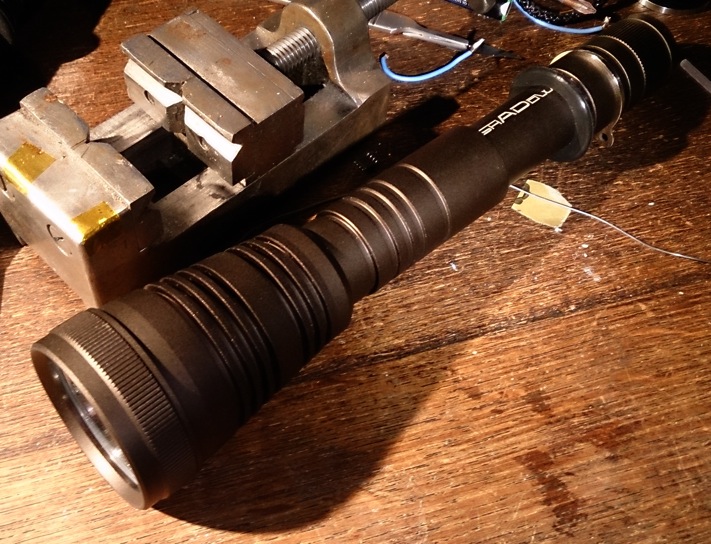
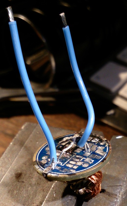
It is the Shadow TC 300. I removed the driver and led board, cleared the driver from components to use it as a contact board. I tried to make every electrical path nice and thick for handling big amps. Soldered the minus led wire around the corner of the contact board directly to the brass contact ring, soldered some solid copper wire through 4 via's of the positive battery contact plate and soldered the plus-ledwire to that, and used copper braid to enforce the conductivity of the + contactplate spring:
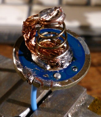
It doesn't look pretty but it sure can handle some amps  .
.
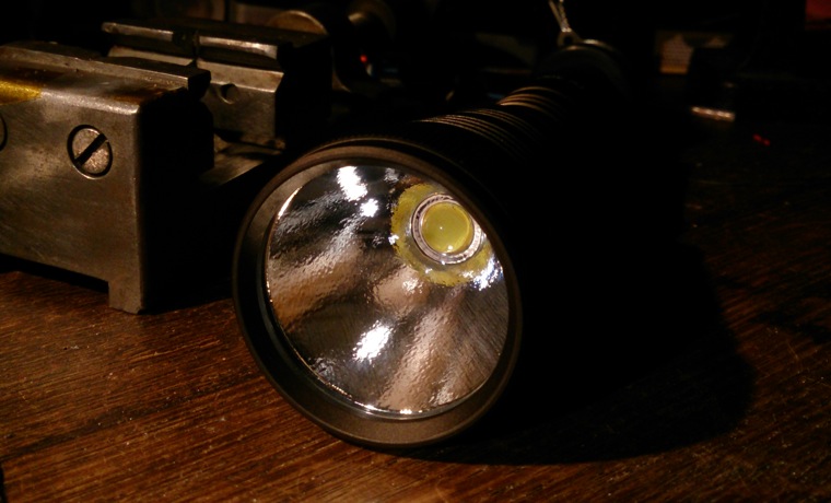
So here it is with the MT-G2 on the Noctigon in place. A weak spot is the reflector directly screwed against the top of the led itself, ruining the thin layer of silicon around the dome, it does not ruin the performance of the led, but eventually after screwing it too tight the light shorted somehow. The tests were done already by then.
The first thing I did was to put some fresh loaded Panasonic CG18650CH (IMR) cells in it, and measured tail current without switch: 8.5A . I decided at that point not to improve the conductivity of the switch spring with copper braid, and measured with the switch into the circuit: 5.6A, that is more acceptable to me . I took a beam shot from three meter from the wall, the first is how it actually looked the second one is underexposed to show that it actually has a nice hotspot:
Here's a video of the first two minutes measuring ceiling bounce lux. Multiplied by 20.9 it gives a lumen indication (so at start that is 2970 lumen). I stopped the test when the head got too hot to touch.

The smoke coming off the lens are evaporating fingerprints that I forgot to wipe away  .
.
In the middle of the night I dared to film a very quicky beamshot into the neighbourhood, it is over before you start paying attention :

After some playing around I became a bit more confident about the light, charged the batteries to full again and did a stamina test of 10 minutes at room temperature without extra cooling (even not with my hand). I measured the output:

Afterwards the light was way too hot to touch, but not blistering hot. The batteries were also hot but not that hot, the voltage was 3.74V each.
I also checked some protected no brand Li-ions (non-IMR) that came with a very bad headlamp I had to review (EDIT: removed some unneccesary grumbling  ), and it still runs at 4.6 A on those (initially).
Concluding I must say the MT-G2 runs quite happily on two 18650 IMR's direct drive. Now I have to repair that switch (or I may not do that and go back to small EDC flashlights where my heart lies ) EDIT: repaired, post #36
Hope you like the results, and that the information is somehow useful to someone.
Nice djozz. I’ll have to watch the vids when I get home.
Thanks MRsDNF, and I just figured that the tail-threading of this Shadow is anodized, so I can just bypass the switch and make it a tail twisty .
Great info djoss. Emboldened by this thread, I tried 2S protected NCR18650A’s last night DD. Only pulled 3.65 amps and the emitter seemed quite happy. I know it’s quite wimpy compared to what you’ve been doing, but it was a big leap of faith for me. I only have 3 of these emitters right now and I love each one of them.
Now I’m wondering if 2S2P with the same cells would work too. It seems that voltage sag would still be the same given how much current these emitters seem capable of handling. I will it out try tonight and report back.
I like that plan, and am curious about the results, you'd expect the current to be a bit less than double what you get with 2S because the Vf goes up a bit with the higher current, but who knows what happens....
Am I reading this correct? 3K lumens with 2A @ 6v?
Nope, red line is lumens, blue is current.
Thanks, I didn’t scroll to see the legend.
So it’s 5A@6v (30W) for 27-2800 lumens if I’m now reading it right.
Well, I tried it, but I think I wasn’t getting good battery connections. I really hodge-podged it with tape and wires as I had no battery holder for 2p2s. It was only getting 4.5 amps at the emitter at that was at start up. It dropped down to around 4.1 within a minute or two.
I will try again another day.
I repaired the MT-G2-modded Shadow :-) Here is some more on the repair and the (altered) mod:
First I put a cardboard spacer around the led, just a bit thicker than the led-base. the reflector is now tightened against the cardboard and not against the led-base (the short I had appeared to come from the led-base, and that actually means that if you scrape away some of the silicone around the dome, it is likely possible to solder your led wires on top of the led, like with the XR-E).
I decided not to bother with a switch anymore, the tail threads were anodised so I shorted the switch out, it is now a tail twisty light.
Thing is, with the CGR18650 it now it runs the full 8.6A which is not very healthy in this host: the head gets bleeding hot in seconds. On switching twisting on, I measure 3400 lumens, but within the minute the output has fallen to 2700 lumens and descending more slowly from there. So to run the MT-G2 at this 8.6A a bit more reassuringly you need a much bigger host with lots of fins (well, we kind of knew that already). Some other numbers with these batteries: throw just after start-up is 29klux@1meter, power is 60W, efficiency of the light is 56lumen/W, and after a minute 45 lumen/W. This efficiency at this output is actually not bad (I have build a XM-L2 (5A tint 80 CRI) on copper board flashlight at 3A that measures -the battery I estimated 3.9V under load- 66 lumen/W, if it was cool white it would have been 80lm/W).
I tried LiFePo batteries as well: A123 1100 mAh x2. The output gets really mild on those: I measure 2.1A, with 1136 lumen at start, 1072 lumen after a minute, and stable from there on. These batteries should last for half an hour but there are higher capacity LiFePo batteries around. The host gets luke warm. Efficiency is 82 lumen/W which is really good for a neutral white flashlight.
I do not have two matching normal Li-ions apart from the two unbranded protected ones I mentioned earlier that came with the headlamp. I could just do a current reading before protection kicked in: 5.6 A. I had two seconds for the output: 2500 lumen
I did a better video with the Panasonic IMR's :

So that's all you are going to read about this mod, I will keep the light as it is now: with the IMR's it will generate serious wow from my non-flashoholic friends, with LiFePo's it is a nice and safe light to use and can even be lended out to others :-)
I’ll confirm you can solder to the top of the emitter’s pcb. You have to clean it well though for the solder to take.