I bought my R5-A3 at DX in January. There were multiple posts about the PIC mode mod here but they were random, incomplete and hard to find.
Yes it works with AAs and no there is nothing to worry about on the backside.
I bought my R5-A3 at DX in January. There were multiple posts about the PIC mode mod here but they were random, incomplete and hard to find.
Yes it works with AAs and no there is nothing to worry about on the backside.
Great job E1320. My R5-A3 spends most of its time buried in a drawer because I hate the factory 3 mode selections. I have several XML T6's on 16mm stars that I should be able to whittle down to 14mm and not have to buy and wait for parts. I might need to buy a new soldering iron to get into an area that small.
Did you notice any significant differences in the beam pattern and output? Are there any differences in the heat generated?
Its pushing more amps because the XML has lower resistence than the XPG and the driver isnt a true CC regulated version. Ive seen this phenomenon in several mods with cheap Chinese drivers where Ive swapped lower resistence emitters in place of higher ones.
The brightness appears to be the same but the hotspot appears to be twice as big. It has a really cool looking effect that is much easier on the eyes it almost appears like it has no hotspot at all just a soft floody but very usable beam.
It definitely doesn't heat up as much or as fast. I am not sure if it because the XP-G was over driven and now the XM-L is very conservatively driven or if that it was not heatsinked good before with just screws holding the emitter down and now it is seated very well with adhesive.
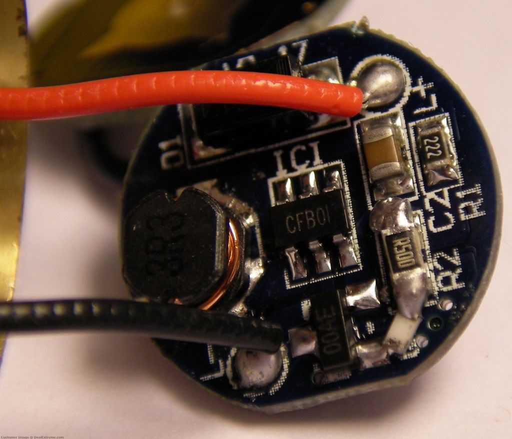
Thanks for the info E1320. I really wonder how that driver is supposed to work with only 1.5v seeing the components of the driver. Or is there any other components which aren't visible on the photo?
Here is a picture of the backside of the driver.
Sorry to resurrect an old thread, but I have to ask: the new connection we make, is it from the leg to that large blob of solder (near the b- marking) or to the tiny pad just below the leg?
thanks!
Hey Devman
That's why I made this thread. You can do both, just blob some solder on the tiny pad but that just connects to the giant blob of solder so you can blob the whole thing with no worries. It is so small it is really hard to just get the pad mine has a giant blob on everything and it works fine.
Thanks! ... wow, three blobs in one sentence... That points to the kind of workmanship I actually have the skills for. woohoo!
Yeah .. I read this and thought HUH? where are the markings you're talking about ? I never saw any circles and had no idea what you were talking about ...But I hadn't yet recieved my light yet or tore it apart yet either ..i just am glad to hear someone else didn't get what you were saying ..sorry devman I don't see a B2 either ..E1230 you need to speak really really slowly and have huge arrows and circles. maybe a 20 minute video with an intermission with snacks .. think 4 year old .
I can't see the circles also till today ....

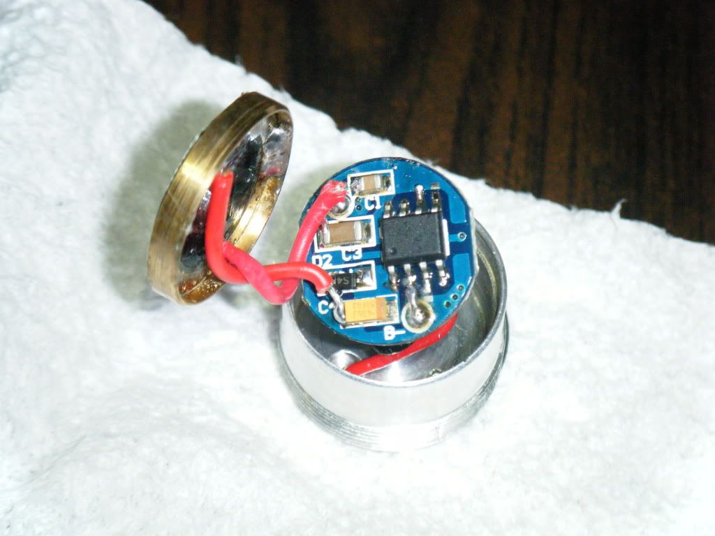
Just saw this thread and wanted to try to activate the HML configuration. I opened the pill, removed the masking tape the driver was wrapped in and saw this:


Its the same PIC, but with a different layout and all legs soldered, so I can't modify it in the given way.
Bought my R5-A3 in August 2010 at DX. Tail cap draw with flammed 14500 is about 1.6A.
Do you have an idea how I can remove the strobe?
Sorry about the next to invisible circles guys, they look really bright on my PC but on my laptop they were hard to see, so I should have assumed some other folks might have the same problem.
Heinzeins that light has a different PIC than the one in this post, it might be doable but not with this method. The light I originally got shipped from DX in January and as far as I know the newer ones and some of the older ones have a different PIC like yours. I have the one from KD on order because that one is supposed to have the PIC that is modable. I will update when I get the light from KD.
Thanks for the info, nonetheless will I put a XM-L in it, just ordered some at Shiningbeam 
I just made the strobe and xm-l mods.
I ended up with a four mode flashlight, High, Mid, Low, Fast strobe. I probably made a poor soldering job.
I noticed that the build quality of the Kaidoman flashlight is really lower than my previous DX version (with a non moddable driver), the crown is not deburred and not perfectly aligned with the body, the tail-clip a lot more flexible.
Ps : I just noticed that I didn't put the blob of solder on the right place ! I shunted the little resistor on the second leg from the left instead of adding solder on the third leg !
I was thinking of getting one [ R5-A3 ] , but realizing there were two different drivers , its sort of pot luck .
Boaz: The B- terminal is there, big white printing silkscreened at the very bottom of the pcb... it's like the only thing in that area that stood out enough for me to reference. although with my solder skills, I might end up blobbling all the terminals together and making it a direct-drive light!
moral of the story? 8.9" netbook screens suck. suck worse than smartphones. suck suck suck.
Ive got the same driver as you, and what a bugger it was to get out. I had to remove about half the brass retaining ring with a dremel tool to make enough room for the driver to slide past it. If you find a way of deleting the strobe on this driver, please let us know. Like you, Im modding mine with a XML.
I noticed that you chipped your inductor spool. I did the same.  My fingers are crossed that it will still work after all the abuse I just gave it during surgery.
I had no problems getting the driver out: I removed the outside plate with an soldering iron and could ecxtract the driver board with my fingers. I'm quite sure the spool looked like this before. I haven't changed the emitter yet, but the XP-G still works perfectly.
I'll let you know if I find a way to delete the strobe, but I'm not very optimistic.
I finally got my R5A3 from KD today and looky here it has the modable PIC.
After my 5 minute solder mod, so ugly but good enough to do the trick.
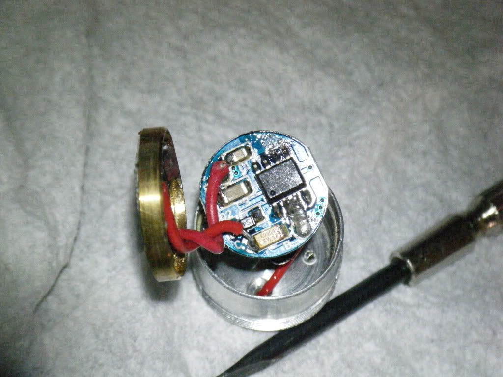
This is a great deal at $14 bucks to have a 3 mode R5 light with no stupid flashy BS. Get one before they are all gone.
Thanks but my driver no longer works. I think mine was made as an experiment. With the brass collar as thick as it was, it must have been pressed in after they inserted the driver. Even after spending ages dremeling the brass collar to make it thinner, it was still incredibly tight removing the board. By the time it came out, all the poking and pulling had taken its toll. Another nice surprise on mine; it came with an XPE! Not an XPG. No wonder it never seemed that bright. I removed the emitter dome to experiment with the beam pattern before removing the star and commencing with the driver removal.
I think a 17 mm driver ground down to 16.5mm will work. Can anyone recommend a good AA/14500 driver?
If not, I might buy a 2800mA 7135 based driver and remove one of the 7135 chips to make it into a 2450mA driver. Even that doenst sound to good given the limited capacity of 14500's and that it wouldnt run in regulation more than a few minutes.
Any thoughts guys?