BTU Shocker Triple MT-G2 with a twist -- Aiming for >100Watt ~9000Lumens -- With external 2S power pack, handle etc...

Yeah, it’s a shame. I had no luck at all in finding spare parts for my Apex 5t6 and there’s quite a lot of those models out there. Even contacted a number of resellers to see if they had returned or broken parts/spares that I could buy. No deal. I suspect there’s just no incentive to make extra parts for customer service type situations and even factory seconds end up being used in making up a batch of second rate flashlights of varying quality that go out on sale.

For the BTU, at the moment i’m thinking more along the lines of shortening the front of the battey tube and machining a new thread inside so it can thread onto the head. Getting the spacing of the tailcap to the body just right once it’s fully seated into the head. Something like my last rendering, I quite like that form factor and it would still give me some limited space inside the body for whatever.
I dunno, I’ll have to put a lot of this aside until I have a play with the host and see what would make the most sense.

You should apply this for fenix flashlight design!

I didn’t know about the fenix competition, thanks.

Ok so I have a bit of progress to report, today I made the trigger clicky and it’s enclosure/mounting.

I haven’t cut the enclosure to the final assembly size/shape but the masking tape shows what the final thing will look like.
Way too risky to cut this now based on estimated measurements!

Inside it’s simply one of those standard 1.5A omten reverse clickies mounted on some random tailcap pcb I had lying around and trimmed down to fit inside the enclosure.
The enclosure I made from a 5v transformer/power supply casing which had a nice little ergonomic lip at the base. I cut this in half and sanded the two halves until I had the width that I needed. Then glued the two parts together, drilled and dremmeled out the hole for the switch boot and put it all together. There’s a backing plate mounted into a grooves inside the case and plenty of hotglue to ensure the switch doesn’t go anywhere.

The cable will run down inside the handle through the middle dovetail groove and the twisty part will take the rest of the cable down to the tailcap. Not certain how I’m going to run this into the tailcap just yet but probably just through it’s own port. Maybe with another connector if I get real fancy, for modularity and flexibility. :stuck_out_tongue:

Also just to be clear I won’t be running 15amps through this cable! It will just be the control switch for the drivers.:slight_smile:

And finally here’s some more renders of the model with the switch mounted. The blue line shows where the cable will be running.


Those MT-G2s are to scale btw! Huge buggers!! :party:

Cheers
Linus

Bit more planning stuff, this time on how I will be tackling the emitter mounting and how I’ll approach sinking some heat into that massive reflector.

Front view showing the noctigons in place and the crazy pattern of necessity for my copper spacers :).

The idea is to have the reflector back sitting flush on these copper spacers and sucking some heat off the pill.
Would love to be able to machine a nice copper spacer/gasket for this but I’ll have to make do with what I can find.
So far I’ve found some 15x15mm copper squares on ebay available in various thickness so I’ve ordered a bunch of different packs to combine and hopefully cover my spacing needs.
Going by my measurements and Noctigon/Cree datasheets I should need a spacer height of 2.3mm to just clear the top of the MT-G2 baseplates with the reflector. (The emitters pcbs themselves will probably be glued down)
So I’ve ordered 2mm, 1mm, 0.3mm and 2x 1.2mm sets of 10 spacers so I should be able to cover any distance that’s 2mm, 2.2mm —> 2.5mm in 0.1mm increments and even reach to 2.7mm if get some crazy tall noctigons for some reason. :stuck_out_tongue:

Of course they’re all separate little squares so once I’m happy with the fit I’ll probably try reflowing them together. Maybe in a kind of press or something that can be heated while keeping the components under good pressure to get a nice tight single piece copper disk. This sounds like a nightmare by I’ll give it a go :slight_smile:

In the end I just hope to be able to sink some heat into the massive bulk of the BTU reflector, because in stock form it looks like there is very little thermal pathway between it and the body/pill.

For the emitter wiring I’ll need to drill 6 holes through the pill surface to get the wires close enough to each pcb solder point. I figure drilling at an angle from the places shown on my model I should just about be able to drill through the thinner part of the pill and gain access to the driver cavity without going through too much solid sidewall.
In there I’ll have to see about adding some more thermal mass that’ll bolt to the bottom of the mcpcb mounting plate.
Depends on how much space I need for drivers and such.

For the drivers I’ll be running a separate set of 7135s/(slave driver) to each emitter so while the whole circuit will still be in parallel I should gain some per emitter regulation and avoid any issues with differing vF or resistances.

So that’s it, let me know what you guys think and if anyone has attempted something similar that I can learn from.
Especially with regard to those copper spacers and reflowing stuff like that together.
Cheers

Still here reading. Interesting.

Wow! I was thinking of getting a copper screw to replace the standard screw that goes into the reflector, thinking it will heat sink from the pill top to the reflector. Getting direct contact from the pill top to the reflector is a little beyond my capabilities, but I gave it some thought, wondering if even thermal pads stuck in there and compressed on contact would help, but don't think they are very efficient.

Still not sure how you will get the "perfect" spacing from those copper inserts to the reflector - you want the reflector sitting down to get the best output of the emitters for sure, not to mention how perfectly level they must be. Maybe you will use some quality thermal paste in there?

yup it may all go horribly wrong! :wink:

The biggest problem will be getting those copper pieces together and perfectly flat for sure. I imagine there will be a lot of cutting, sanding and cursing at whoever stenciled out the pieces in the first place.

If I get it just right the reflector will be fully seated on the spacers and the emitter domes will be as far into the reflectors as possible without themselves actually being pressed down on by the reflector rim. I want the pressure, if any to be on the solder points on the pcb. If I then find I need to move the reflector out a bit more because the focus of the emitters is wrong I should have the ability to do that by changing around or adding on some more of those copper spacers.

And yes there will definitely be a generous amount of thermal paste on all the contact surfaces. :slight_smile:

With regard to the copper screw, that’s a really good idea. I need to look at that, maybe I can find a high-copper brass bolt to replace the one that’s in there. Can’t hurt :slight_smile:
You wouldn’t happen to know the thread size and length of the stock bolt would you?

Cheers

Crap! Actually I worked on a Shocker mod'ed by someone else and they left the screw out! I found one that fit well, but think it was a US size. All I had to do was cut it down. Hhmm, can't recall the thread size... Was thinking of brass too, but like you said, high copper content would be better I assume.

Running these Shockers at 6A to each emitter does get warm pretty quick, so would think getting that reflector to do more heat sinking is good, but your amps have to be up there, because 4A is no problem with the pill and pill area.

No worries, I’ll take some measurements once I get the real thing apart.

Silicon Bronze seems like it would be a great option for a bolt. Not cheap though even if you can find the right size :slight_smile:

Bit of an update on the battery pack.

I received the lipos today and decided to get the battery pack assembled to a servicable/testable state.
I ended up going a slightly different route for the lipo packs, rather than the two Turnigy 5000mah 2s1p 20c softcase packs I chose to get two Turnigy 6000mah 2s2p hardcase packs with a 25c discharge rating.


Turnigy 2s2p 6000mah hardcase

I am actually not too keen on parallel wired cells in preassembled packs because I like being able to see directly how each cell is doing, but in this case it ended up being the best option.
This was mostly down to size and capacity, with the longer but thinner 5000mah packs I could have theoretically fit 4 in there but it would have been too tight to realistically do the wiring without soldering the packs in permanently. With the 6000mah 2s2p packs I have more space for connectors and wiring at the top while also filling up the vertical space fairly efficiently and getting some more capacity in there with less hassle (compared with two 5000mah packs).
The hardcase is also quite nice and means I don’t have to worry about potentially damaging the foil packages of the bare cells when jamming the lid shut. It’s quite a tight squeeze to get things closed up. :slight_smile:

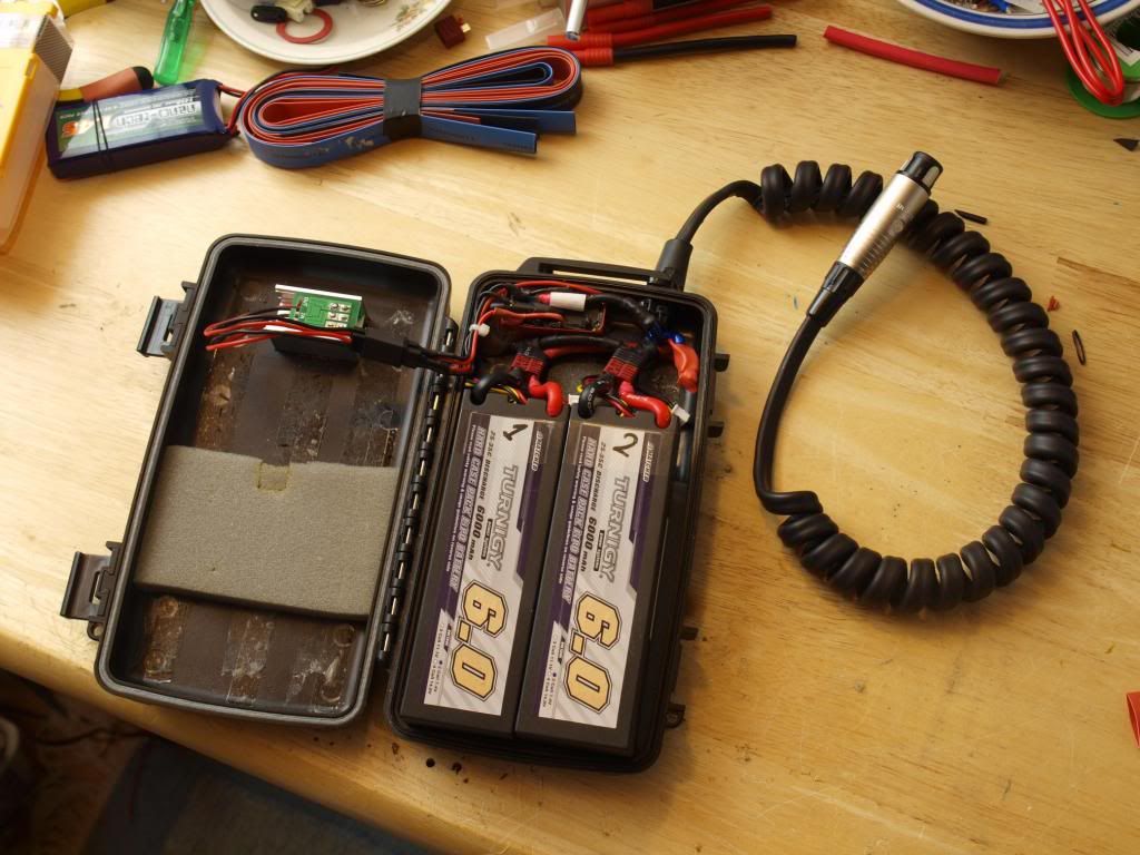
Here’s the assembled pack as it currently stands, the two 2s 6000mah lipos connected up in parallel with deans t-connectors.
Above it are the twin relays also hooked up in parallel. They feature 6v coils, with a rating of 12Amps each and are triggered on by the master toggle switch on the outside of the pack.

Still to come is the temperature monitor/alarm and a circuit for automatic low voltage cutoff. Possibly also a short circuit detection, we’ll see.
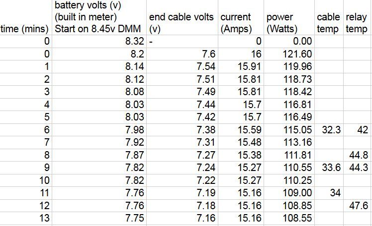
But for now it’s ready to test.

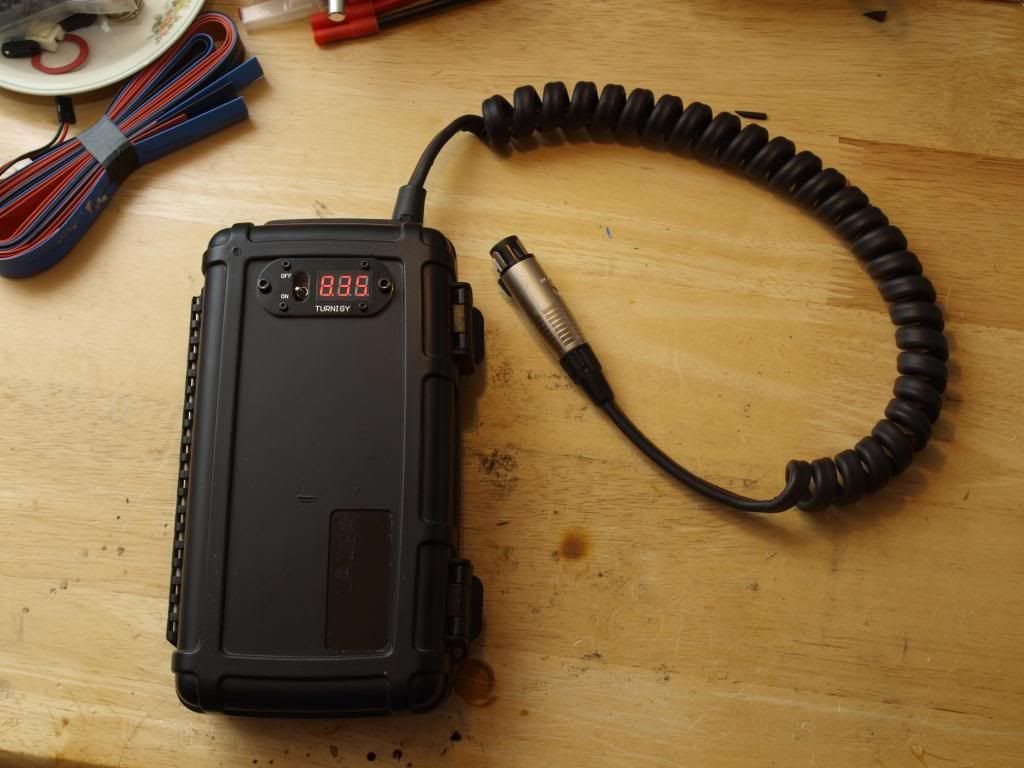
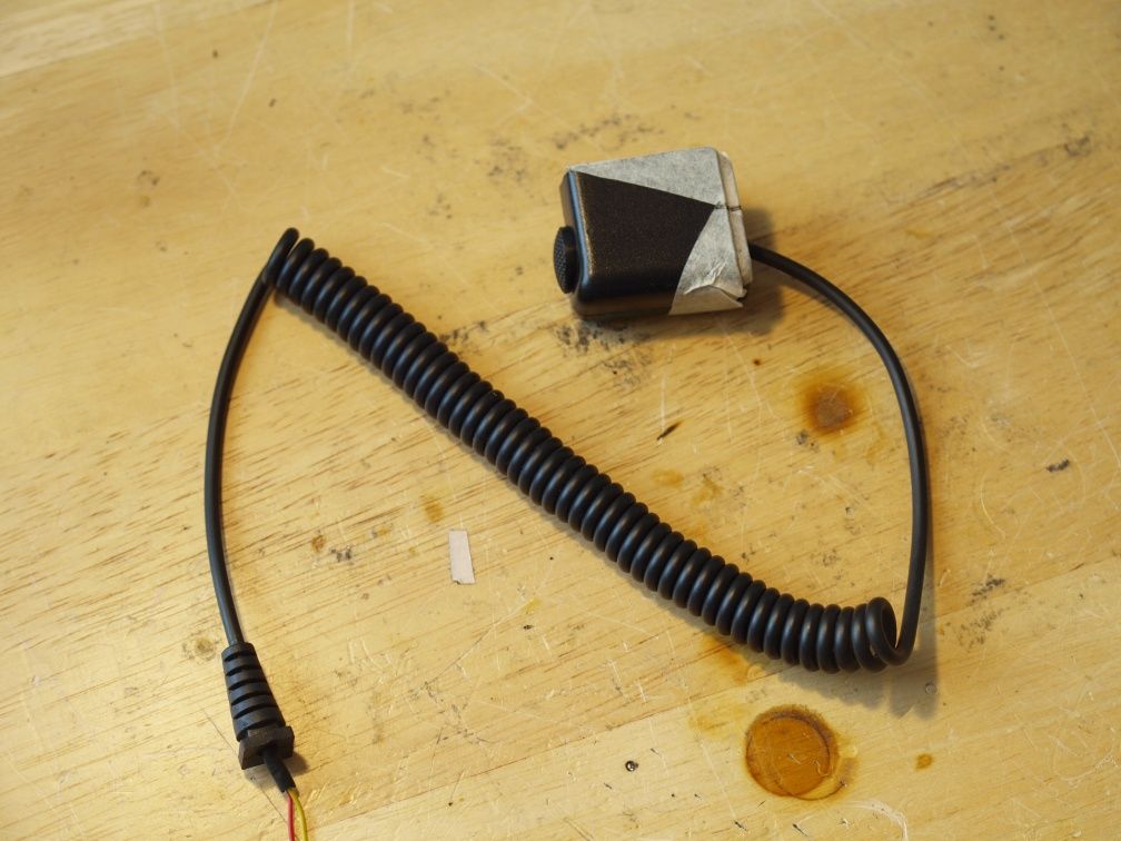
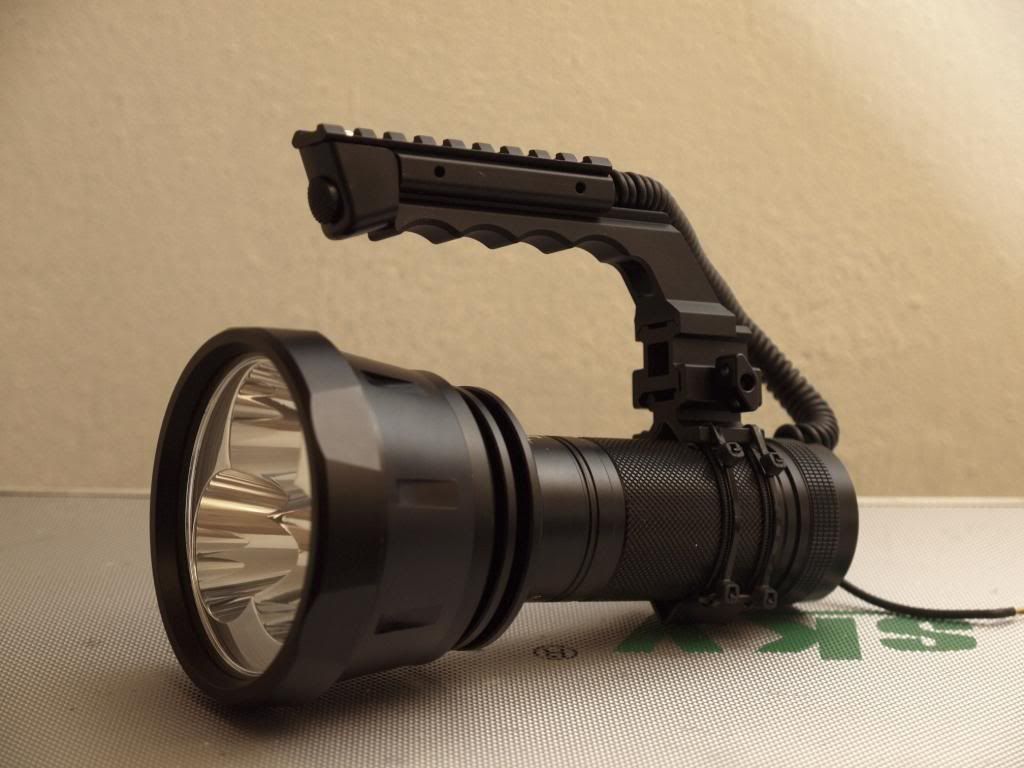
Another difference to the last time I showed the pack is the much thicker coiled power cord. The 18awg cable I was using before just wasn’t up to the task and at 15A test currents it was wasting a stupid amount of energy through high resistance. This new cord is based on a 14awg copper stranded speaker cable and is performing much much better. The material of this speaker cable wasn’t keen to coil under heating so I had to shrink wrap it first them do the coiling and that worked out really well. It’s quite a stiff coil that likes to return to this position, much more so than my first attempt with the thinner cable.

It also weighs a heck of a lot more, but well… the lipos aren’t exactly light either! :slight_smile:

Speaking of which the total weight of the pack is now 1.36kg! Which means you’ll definitely notice its presence on the belt, and also means I need to beef up that belt clip to something more substantial.

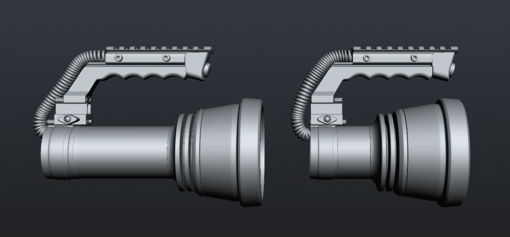
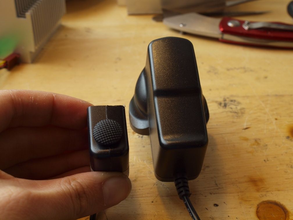
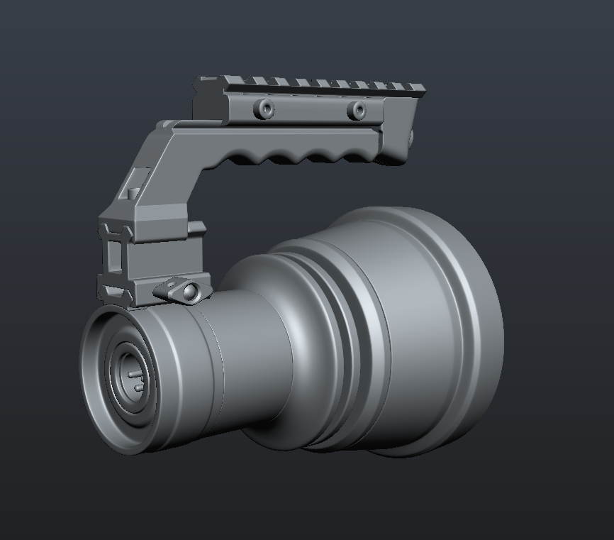
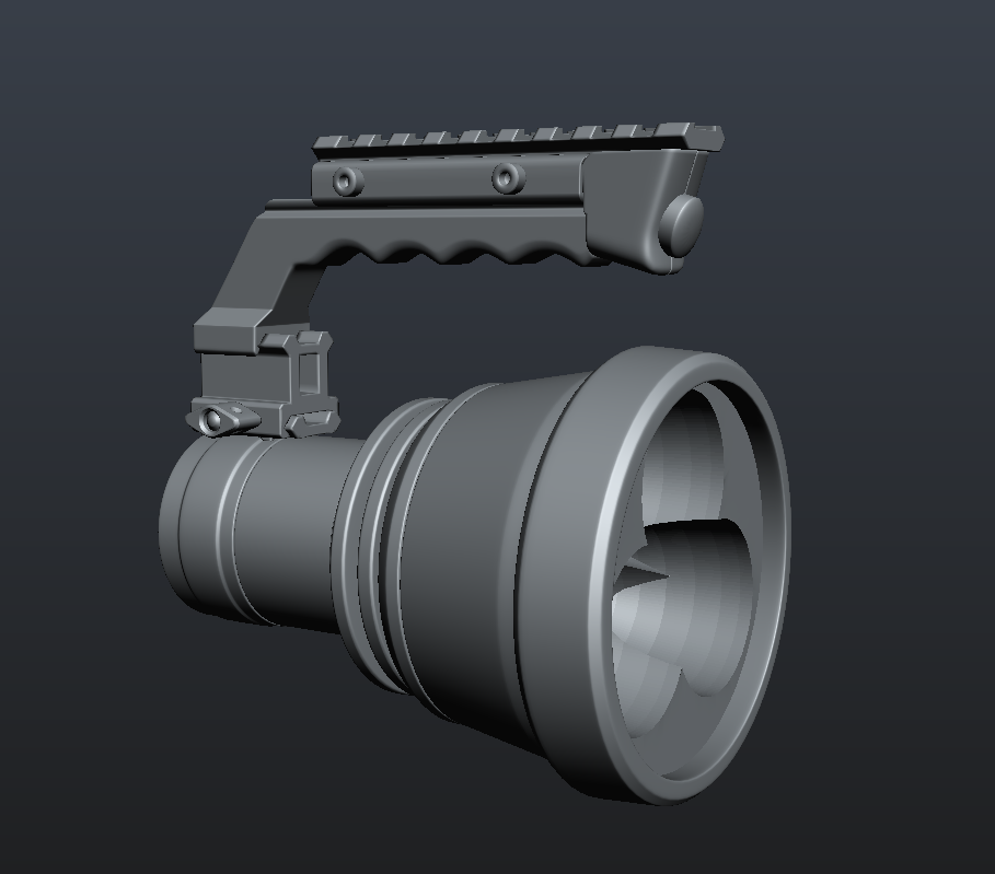
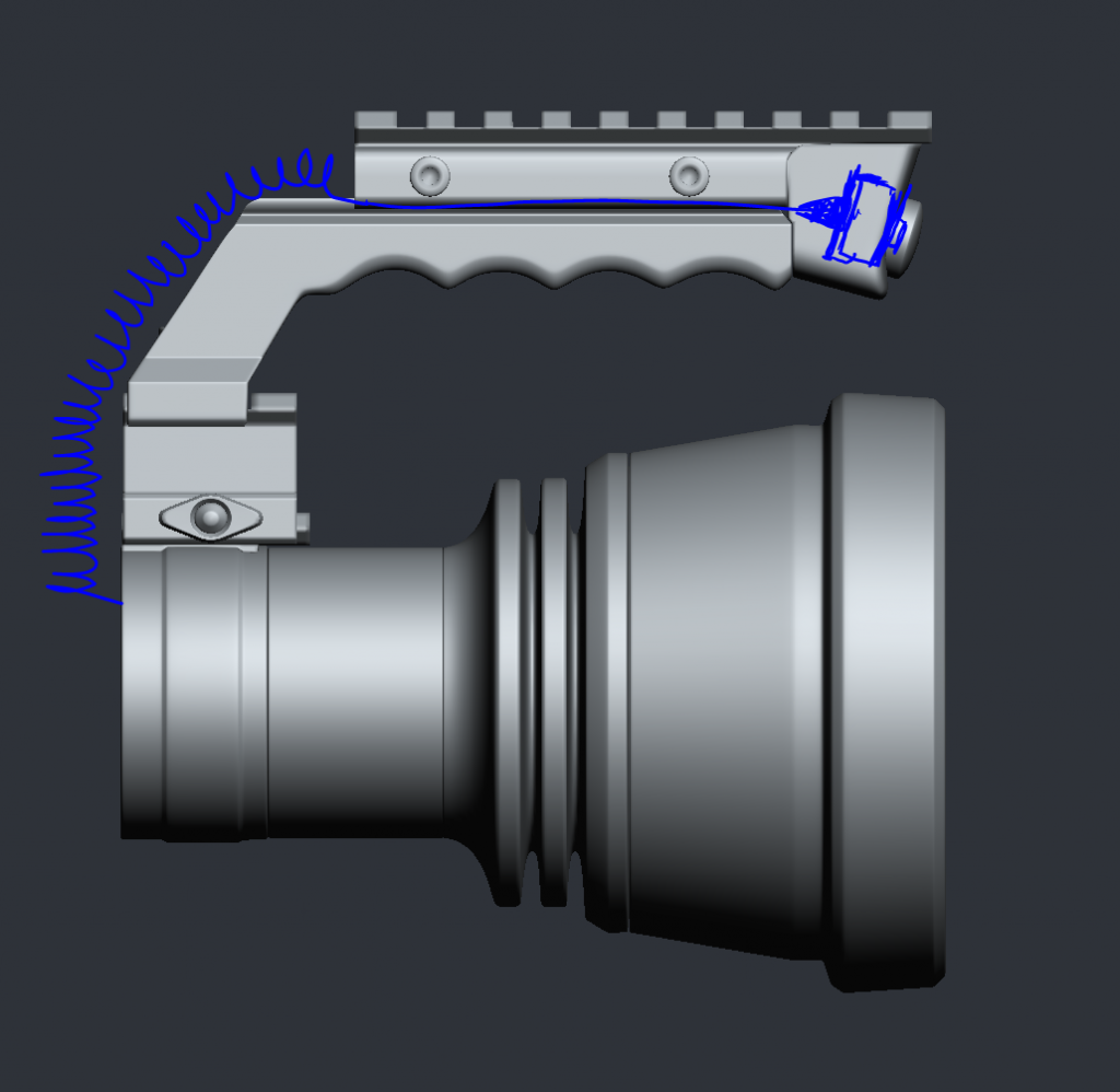
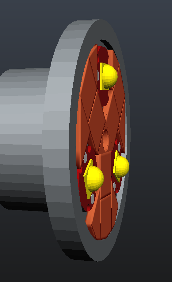
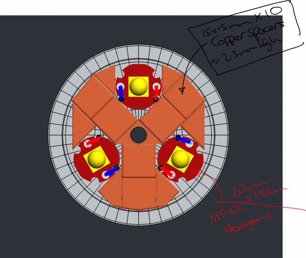
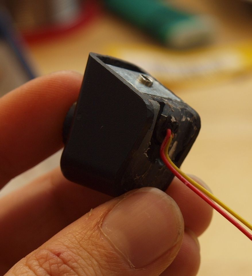
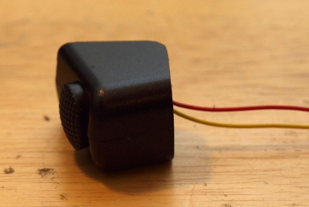
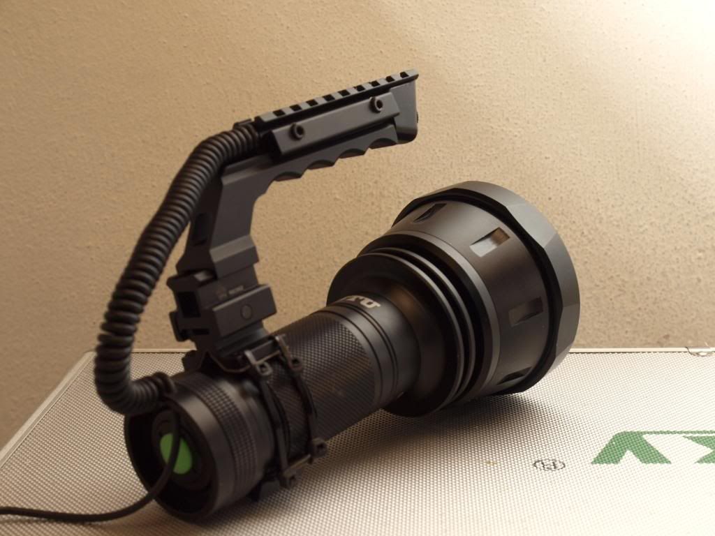
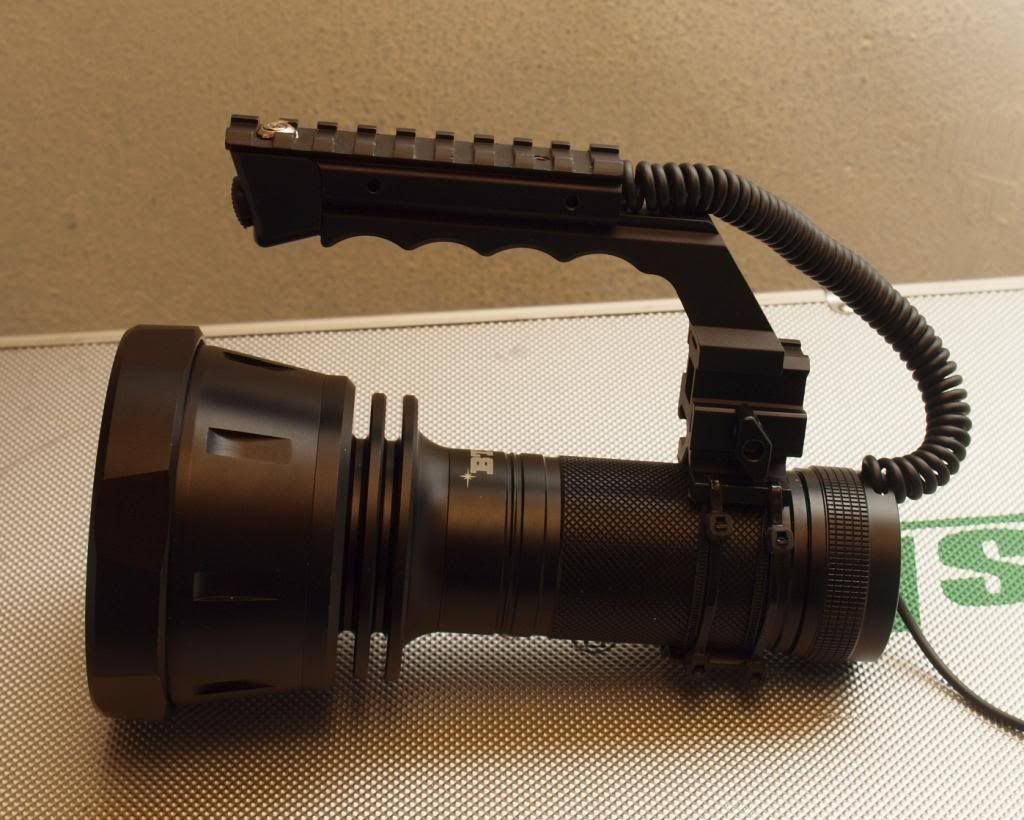
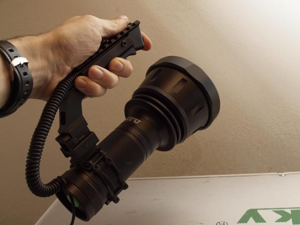
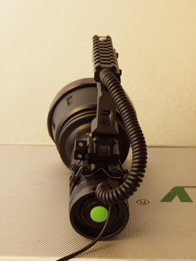
Finally a couple more renders showing how I plan to run the switch wiring down the back of the light.

The parts are starting to trickle in now so I can’t wait to start assembling the final thing.

Cheers
Linus

I’m more excited for the outcome of this build more than any other build I’ve seen on here, bring it on!!!

Feeding Chain:
MEGA Shocker (this build)
Super Shocker
BTU Shocker

Did some battery pack run-in tests and here are the results.

They’ll do just fine at 15Amps, in fact that’s what I’m using to do these “gentle” run-in discharge cycles because it’s just a little above 1C load for each lipo. Basically nothing, which means there’s hardly any voltage sag.

In the chart I measured battery voltage based off the meter built into the pack and also took the voltage at the end of the coiled power cord using my DMM. This is important here because of the fairly substantial resistance losses in the cable and I need to know what voltage range is actually going to be available to the drivers.
You’ll see I still drop around half a volt across the length of the cable but it’s miles better than the 18awg wire I was using before, that was dropping over 1.5v in the same test scenario.

At half a volt I should be well within the working range of my target drive current for fairly long regulated runtimes even at ~5Amps per led.

I’m using the vF/I graph from the Mt-g2 torture test done by djozz to get an idea of where I need to be to get the results I’m after and if those graphs are reliable (which I’m sure they are) I should be well on track for >15A high and around 9000lumen emitter output.
Possibly with some source voltage headroom to go even higher for Turbo mode, 7Amps per emitter sounds entirely possible but probably not for very long.
I also need to keep driver and emitter wiring losses in mind but the cable is by far the biggest hurdle to overall performance.

In any case as long as my source voltage stays above 7v I should be able to achieve 5A per emitter quite comfortably and as this test shows, the voltage at the end of the cable is still 7.16v at 13mins into the test.

I didn’t want to discharge the batteries too far on this first test so I called it a day at 13mins, but I’ll do further discharge tests once I’ve cycled the packs a few more times and see how long I can maintain this voltage range before dropping below 7v.

RMM: There looks to be a place at the top of that list for an ULTRA Shocker, who’s on the case? :bigsmile:

Linus

Nice work Linus. One MTG-2 at 5 amps pumps heat like you would not believe. Cooling will be the biggest headache here. Keep it up. :slight_smile:

Oh I’m sure heat will be my biggest problem. I fully expect my turbo mode to be a short burst only mode. :slight_smile:

I’m beginning to realise just how much 100watts of heat is and how difficult it is to dissipate even on my substantial resistor bank. Had to bring in a 12cm fan to keep things in check for the test. :stuck_out_tongue:

What’s this!. A real life/non digital flashlight in this mod thread! Never thought I’d see the day :stuck_out_tongue:

The BTU host finally arrived along with most of the parts I needed for the handle. So I got stuck into assembling the handle and finalizing the trigger switch before putting it all together. I was really keen to see if this thing would actually fit as I had anticipated.

So far so good, and thanks to the 3d model no real nasty surprises.
Here is where it’s at right now. :slight_smile:

The handle is temporarily mounted to the battery tube using a two part barrel scope mount with picatinny rail top, thanks for this goes out to the inept Kaidomain shipping department who sent me this completely by mistake instead of a plastic reflector I had ordered. Thanks guys, it actually came in much handier than the reflector would have as the actual rail part that I plan to use is still in transit. :slight_smile:
Ultimately with the proper rail in place the handle will sit about 15mm lower than it currently is but other than that it’s very close to how I want it.
I’m still debating whether to mount that handle rail to the tailcap as in my renderings or directly to the battery tube. The latter would give me more options for a secure attachment while the tailcap option would probably make boring out the tube for 4x18650 cells easier. The tailcap is even less spacious that I expected and drilling two m4 holes to mount that rail may not be possible anyway so it could be an easy choice in the end. We’ll see.

-


For mounting the switch I cut the case down to size, added a metal plate to the top with m3 threaded hole and drilled a countersunk hole through the top handle rail to bolt it securely into place. Sounds easy and straightforward doesn’t it. :stuck_out_tongue: It really wasn’t and gave me all sorts of headaches but in the end I got it potted with epoxy and very securely mounted. :slight_smile:
Works well but I really hope the switch won’t fail anytime soon because getting it back out to replace it would be a nightmare…!


In any case the handle feels really good and offers a steady hold of the bulky light, the trigger switch is easily accessible by index finger and with this placement of the handle and the bare torch host the whole thing is also quite nicely balanced.
Really pleased with it so far and I think it looks pretty cool as well, it’s clearly cobbled together but still looks like it means business :slight_smile:


Still lots to do before I even think about the guts of the light. Next up is the tailcap and figuring out how best to mount the XLR socket inside. Should be fun :stuck_out_tongue:

Cheers
Linus

Wicked. Totally wicked.

J)

I hope those cable ties aren't your perma solution.

Going the full nine yards, you should be able to find a way to get some short metal tube (prob around half the length of the original battery holder), thread it and mount that handle with some bolts.

There’s no problem that can’t be solved by cable ties! :wink:

The whole handle mounting is totally temporary, like I said even the rail mount I’m currently using isn’t what I will end up with. It’s just a scope mount from Kaidomain that happened to arrive in the mail by accident and I put it to use since it had a short picatinny rail on top that I could easily mount my handle riser to for testing. Works surprisingly well though and gives me a chance to try out different handle mount configurations before I commit and start drilling into the BTU.

Ultimately I will be bolting a short, relatively flat picatinny rail onto the body of the light which I will then mount the handle riser to directly. Still not sure if I will try to attach this rail further back on the tailcap as I planned in my 3d models or if I will drill the bolt holes directly into the battery tube as in the current handle configuration.

Or… as you say I could use the current scope mount, ditch the temporary zip ties and figure out a better mounting for it that would be sturdy but also non destructive to the BTU body. I was thinking along he lines of replacing the zip ties with thin metal rods with threaded ends that I would bend around the battery tube/body and bolt/tension to the scope mount plates with a set of lock nuts.

Lots of options at the moment :slight_smile:

Through all the BTU threads/posts/pics every time I think to myself “that is a big light… and I need one.”

But that picture of you holding onto the handle put it more into perspective.

I did a double take and it made me remember this ridiculously large shoulder-able halogen spotlight I was given some 5-7 years ago. There isn’t really resemblance, seeing a flashlight with a handle just made me remember it.