Would u have a pic of the stock heat sink ?
You mean the pill/finned section of the light?
This is an amazing build. And yes, those SOIC clips can be a pain. I've gone through a couple 3M ones out of frustration when they wouldn't connect. Congrats on getting the programming working!
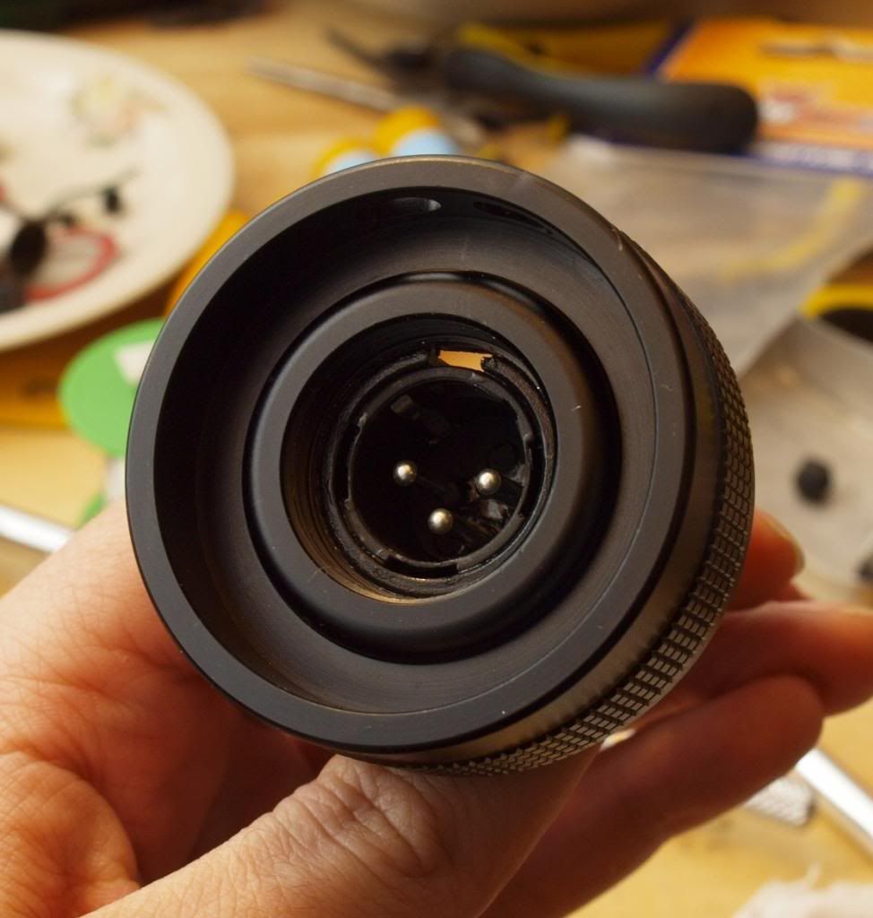
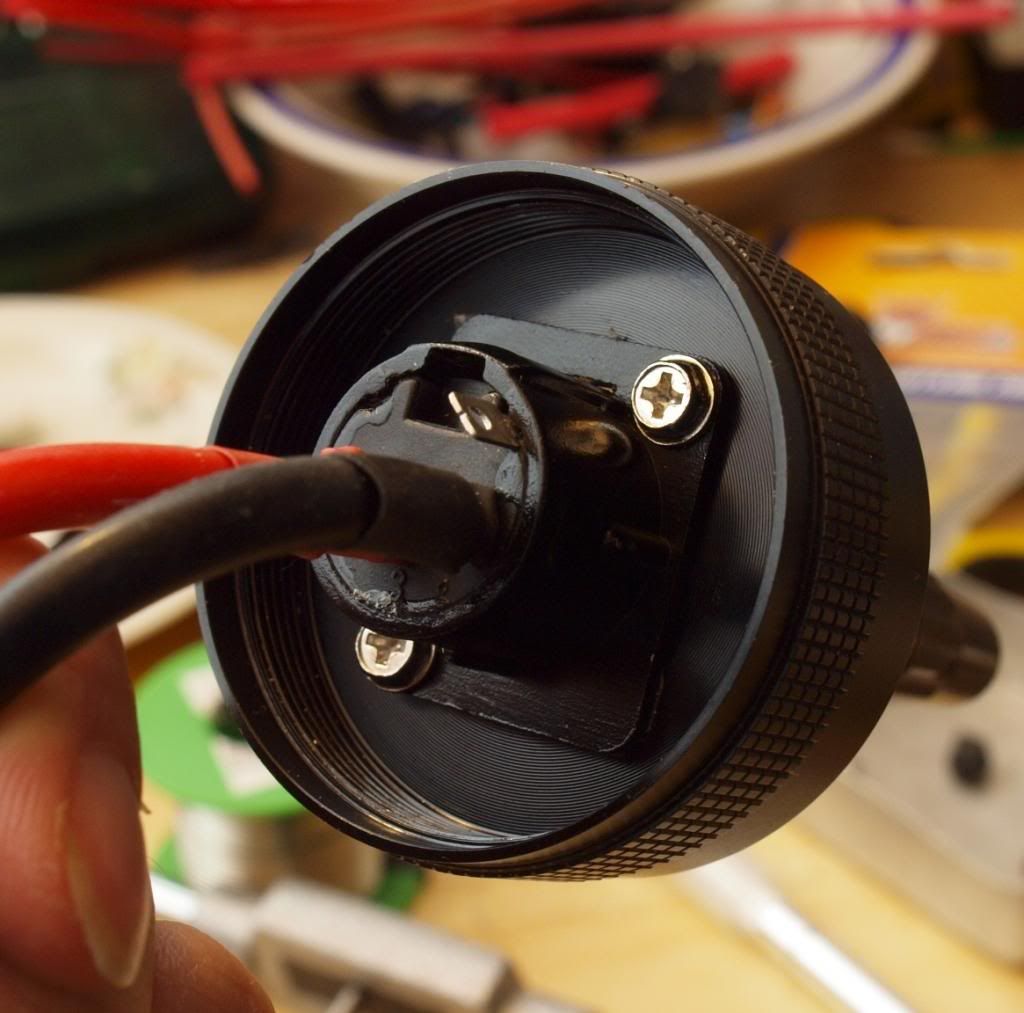
Small update on the Tailcap.
I reamed out the switch-boot opening to accommodate the XLR male socket, then drilled/tapped two holes from the inside and bolted the panel mount socket into place, nothing too complicated.
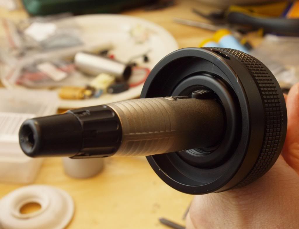
If I decide to go for the optional internal 18650 power I’ll probably need to mount this panel to the outside of the switchboot opening instead. Otherwise clearance inside the battery tube is going to be tight.
But for now I’ll leave it like this.
-
It works good as it is but there’s a few things that could be improved.
When testing with the battery cord I noticed that the current XLR plug coming from the pack is a little long and undergoes a far bit of leverage force with the heavy cord hanging off it. Also the plastic internals and especially the plastic retaining ring on this XLR socket aren’t really inspiring too much confidence in reliability. I’ve got some shorter plugs and an all metal socket on order which will hopefully make the setup more compact and sturdy.
Can’t wait to get those MT-G2s now! ![]()
yes
Sure, I’ll take some next time I have the light apart. Anything in particular you want to see?
Just a pic of it with the driver would be great
Here’s some photos I took today of the head disassembled and showing the “pill” section in detail.
Hope they help. If you need any specific dimensions from any of this stuff let me know.


The “pill” is a single piece of aluminium but is mostly hollow. The driver cavity is massive and there is only a 2mm thick plate seperating it and the area the emitters sit on. It’s actually quite light, (comparatively hehe) especially when compared to the reflector but it’s not all bad news since the emitters actually sit on the outside of the emitter shelf. This is milled out of the solid walls of the pill and the the fins are directly below.

I also wanted to do a direct comparison between an Ultrafire C8 reflector and the BTU reflector array since that seems to be a common comparison people make.
I’ve seen people make the assumption that the BTU reflector is basically like 3 C8s side by side and extrapolate estimated throw figures based on that.
Ultimately it’s not a fair comparison because the BTU reflector cups are both wider and considerably deeper than a standard C8 reflector.
I don’t know exactly how much this affects any throw calculations or whatnot but it’s something to keep in mind ![]()
- BTU reflector size is 48mm deep x 43mm wide
- C8 Reflector size is 31.5mm deep x 38mm wide


The C8 reflector feels like it’s made of paper after handling this beast! ![]()
Cheers
Thanks for the comparison Linus! That explains the throw this light has.
Thanks Linus for the great pics and info u gave me, So i bought one and making another project cant wait
Sure no problem, look forward to seeing what you come up with, any hints?
104mm aspheric lens with a waiven collar,copper heatsink, next is finding a good 4A driver with 3 modes
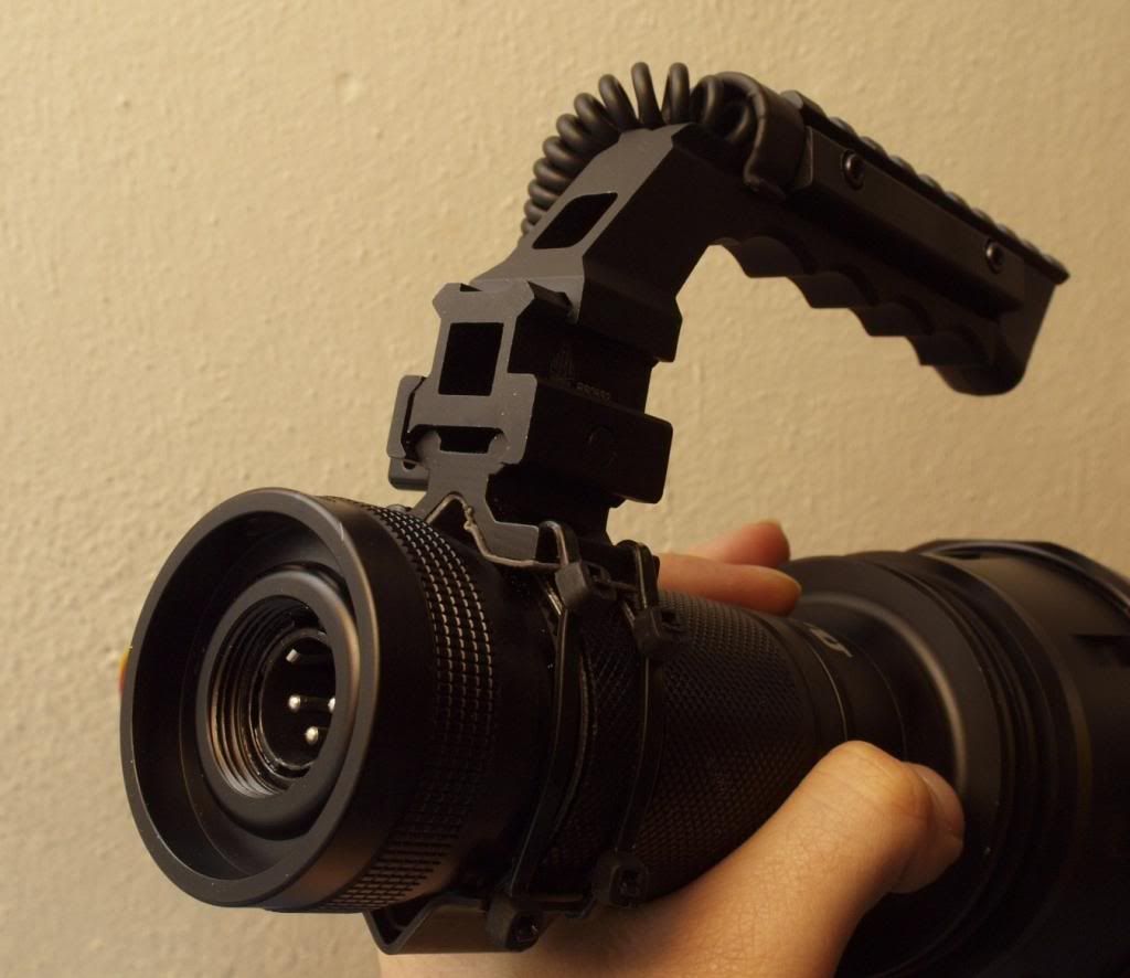
That sounds very fun! Make me a second one so I can strap it onto the top of my BTU. ![]() Crazy flood and throw in one. :bigsmile:
Crazy flood and throw in one. :bigsmile:
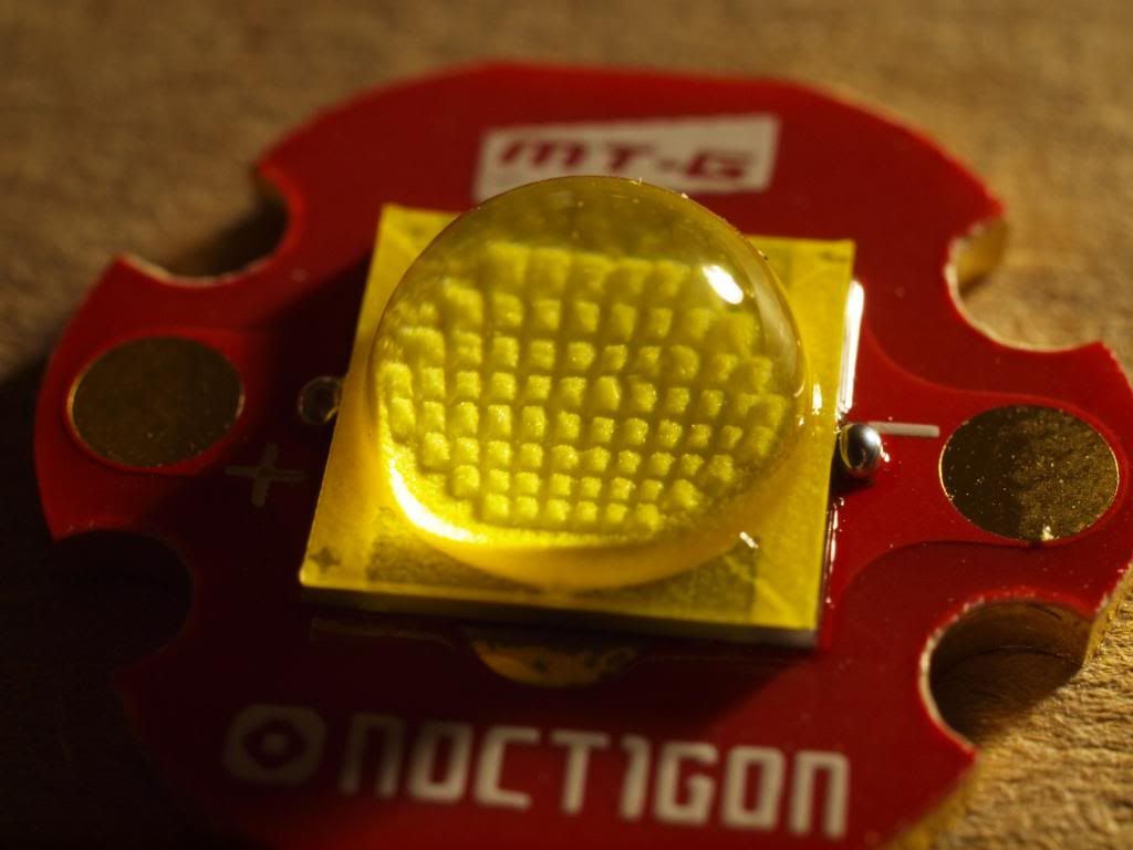
So… finally, finally after 39 days of not very patient waiting I have myself some MT-G2 emitters on noctigons!
These things are huge and gorgeous. I can’t wait to light them up.
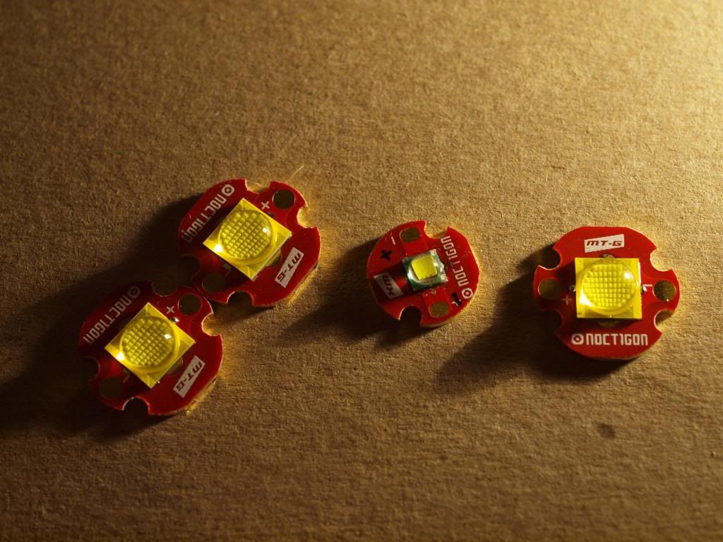
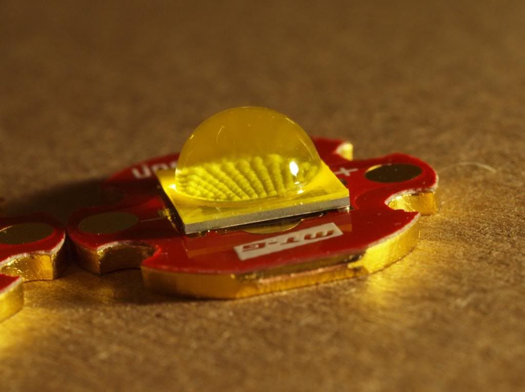
I was a bit surprised to see that this one emitter is not particularly well soldered to the pcb.
It’s not sitting completely flush on the solder pads and slightly cocked up at one end. I wasn’t expecting that from Intl-outdoor but I guess it can happen, shouldn’t be too hard to reflow in any case.
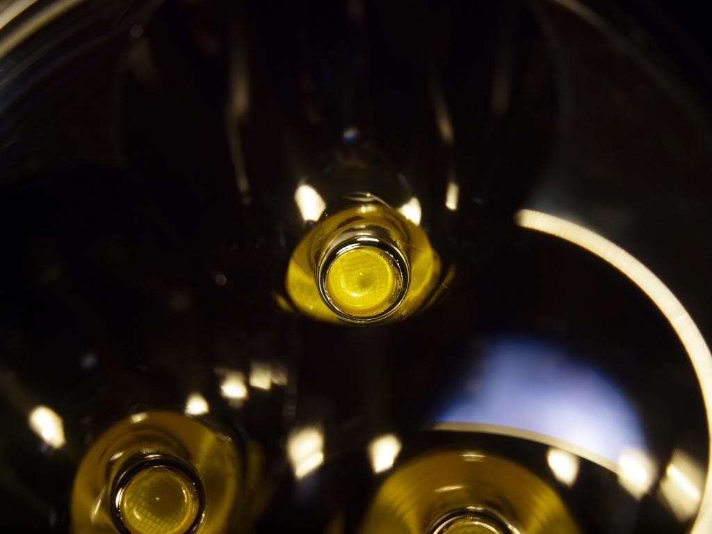
As big as they are, the fit into the BTU reflector is actually a bit looser than I was expecting. Maybe I need to make some centering rings for them.
Just a quick assembly to see how things are looking.
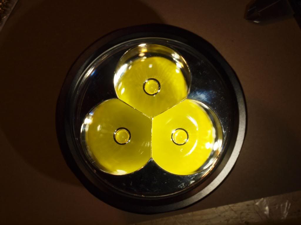
MMmmm triple MT-G2 shocker, time to get cracking on the electricals to feed these bad boys! :bigsmile:
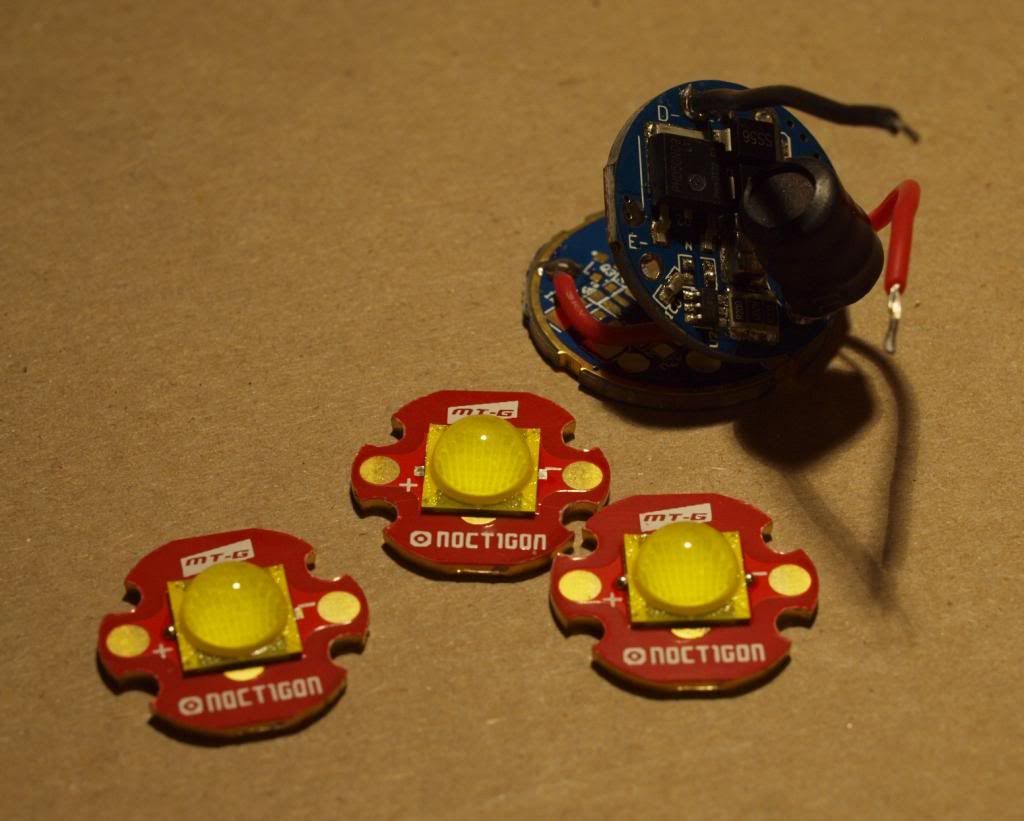
In the same order I also got the infamous 9A IOS buck driver, I won’t be using it to drive the emitters in this light but I plan to do some MT-G2 testing of it to see what’s what. Hopefully with some direct heatsinking it can still make a suitable option for driving a single mt-g2 at over 5A reliably.
My particular sample came with 3x R200 sense resistors on the top of the board and 6x (double stacked) on the bottom for a total of 9. I’m having trouble finding the thread where the sense resistor formula for this driver was discussed but I assume this combination should indeed deliver 9A output to an XML. I’ll see when I start testing anyway.
Cheers
Linus
That reflector with 3x mtg2 in it…

hehe ![]()
So I tried fixing the reflow on that one wonky emitter but noticed that once the solder had melted I couldn’t get it to sit flat either. :~
It sorta rocked back and forth in a weird way like a see saw so I removed the emitter completely and found a chip of what looks like dried fujik stuck to the flux underneath it.
Very strange, must have gotten in there by accident on the assembly line.
I cleaned off the fujik chip and tried reflowing it once more. This time it sat down nice and snug with a hopefully solid thermal path to the pcb. ![]()
Wow - I bought a ton of LED's now from Hank, and only thing I noticed is the annoying solder balls, but I trim them off because they usually interfere with the plastic alignment pieces. Ohh - found out best way to trim is an exacto flat on the surface of the star, and never cut down onto the star -- you can cut thru the trace -- not that I ever did something that stupid ( ).
).
I had the same approach and thought process on this, I stopped using the knife because I was worried about damaging the traces or slicing through the dome if I slipped on the horizontal cut. ![]()
I knew it was going to happen sooner or later so I went back to just taking the solder balls off with a fine tip on the soldering iron. A quick pass and they’re usually gone. Here I’ll just leave them since they wont interfere with anything.
Just playing around with the IOS “9A” buck driver and I’m not very impressed.
-First of all it’s only delivering max 6.7A to the LEDs (input 12v — output to 3 XMLs in parallel), I think I need 3 more of those R200 stacked to the top row to get the advertised output. I had a feeling it needed a double stack top and bottom to get the full output.
-Second the thing gets crazy hot on high even at this lower current. This is a well known problem with the driver, not very efficient and requires serious attention to heatsinking. But I was still surprised at how quickly this thing starts cooking! My guess is these are not really designed for more than about 5A sustained output so it’s no wonder they were burning up in MT-G2 builds running 9A…
-Third it whines louder than any driver I’ve ever heard on Med and Low, really irritating.
-Fourth, it takes about a week to switch modes, click and then you have time to make a cup of tea before the next mode comes up! ![]()
-Finally it has visible PWM flicker on medium and low, not terrible since it’s at a reasonably fast Hz but still visible to the naked eye.
So am I glad I spent $15 on this driver? Nope
I was hoping to find a use for this driver but with the combination of all these issues I’ve lost all enthusiasm for it.
Edit: Saw that they were no longer available from IntlOutdoor, let’s hope he has a better alternative coming!
All those custom 5 LED, 7 LED, and the old IOS 3.5/4.5 and LCK-LED 5A drivers switch modes slowwwwlyyyy also. Think they also have the whining too. Think these drivers just don't like doin driver functions, but do it begrudgingly...  All I'm saying is don't be too surprised by seeing this more often...