That reflector with 3x mtg2 in it…

That reflector with 3x mtg2 in it…
hehe ![]()
So I tried fixing the reflow on that one wonky emitter but noticed that once the solder had melted I couldn’t get it to sit flat either. :~
It sorta rocked back and forth in a weird way like a see saw so I removed the emitter completely and found a chip of what looks like dried fujik stuck to the flux underneath it.
Very strange, must have gotten in there by accident on the assembly line.
I cleaned off the fujik chip and tried reflowing it once more. This time it sat down nice and snug with a hopefully solid thermal path to the pcb. ![]()
Wow - I bought a ton of LED's now from Hank, and only thing I noticed is the annoying solder balls, but I trim them off because they usually interfere with the plastic alignment pieces. Ohh - found out best way to trim is an exacto flat on the surface of the star, and never cut down onto the star -- you can cut thru the trace -- not that I ever did something that stupid ( ).
).
I had the same approach and thought process on this, I stopped using the knife because I was worried about damaging the traces or slicing through the dome if I slipped on the horizontal cut. ![]()
I knew it was going to happen sooner or later so I went back to just taking the solder balls off with a fine tip on the soldering iron. A quick pass and they’re usually gone. Here I’ll just leave them since they wont interfere with anything.
Just playing around with the IOS “9A” buck driver and I’m not very impressed.
-First of all it’s only delivering max 6.7A to the LEDs (input 12v — output to 3 XMLs in parallel), I think I need 3 more of those R200 stacked to the top row to get the advertised output. I had a feeling it needed a double stack top and bottom to get the full output.
-Second the thing gets crazy hot on high even at this lower current. This is a well known problem with the driver, not very efficient and requires serious attention to heatsinking. But I was still surprised at how quickly this thing starts cooking! My guess is these are not really designed for more than about 5A sustained output so it’s no wonder they were burning up in MT-G2 builds running 9A…
-Third it whines louder than any driver I’ve ever heard on Med and Low, really irritating.
-Fourth, it takes about a week to switch modes, click and then you have time to make a cup of tea before the next mode comes up! ![]()
-Finally it has visible PWM flicker on medium and low, not terrible since it’s at a reasonably fast Hz but still visible to the naked eye.
So am I glad I spent $15 on this driver? Nope
I was hoping to find a use for this driver but with the combination of all these issues I’ve lost all enthusiasm for it.
Edit: Saw that they were no longer available from IntlOutdoor, let’s hope he has a better alternative coming!
All those custom 5 LED, 7 LED, and the old IOS 3.5/4.5 and LCK-LED 5A drivers switch modes slowwwwlyyyy also. Think they also have the whining too. Think these drivers just don't like doin driver functions, but do it begrudgingly...  All I'm saying is don't be too surprised by seeing this more often...
Yeah I’m totally new to playing with multi cell buck/boost drivers. I guess I had my expectations set too high coming from the simplicity and downright UI perfection that you can get from a 7135 driver these days. These switching drivers are a whole other story and I’m not very impressed so far, good thing I don’t need to bother with them for this build. ![]()
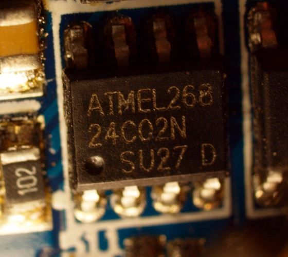
I did notice this driver has an Atmel 268 MCU on it, maybe someone smarter than me can work out how to write some custom firmware to beat these things into shape! ![]()
At first I was complaining about the slow mode switching, and got a response like that's how they are... Just weird the after market drivers are so different than the stock drivers, but we do want more amps and we do want only 3 modes instead of the stock 5 w/blinkies... But the high amps seems like the drivers aren't really designed to handle anyway, so not sure what we are gaining over resistor modding, if it's possible on all these.
This is all making the Task LED drivers look all the better, but I don't see a Task LED driver working for a single high amp LED - think they work well for multi-LED's of 5 or more. Even 3 LED's to max out at 3A each, I'm not that interested in.
Indeed, 3A is only interesting when talking about the 36v version of the MT-G2. ![]()
Let the stacking commence!
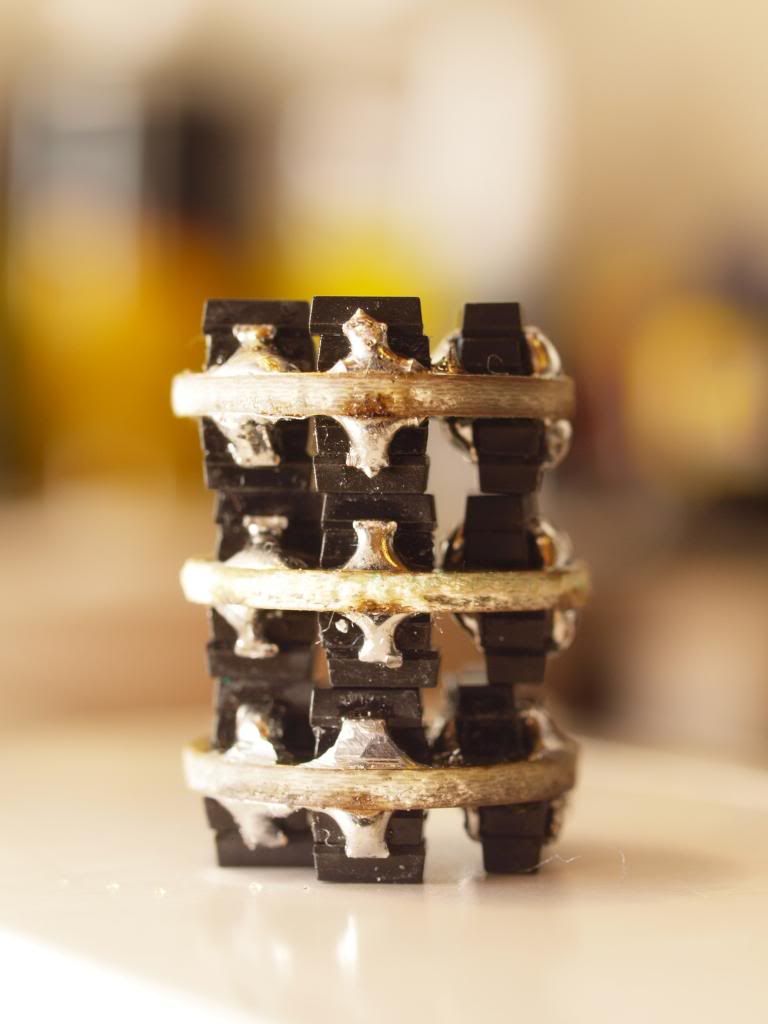
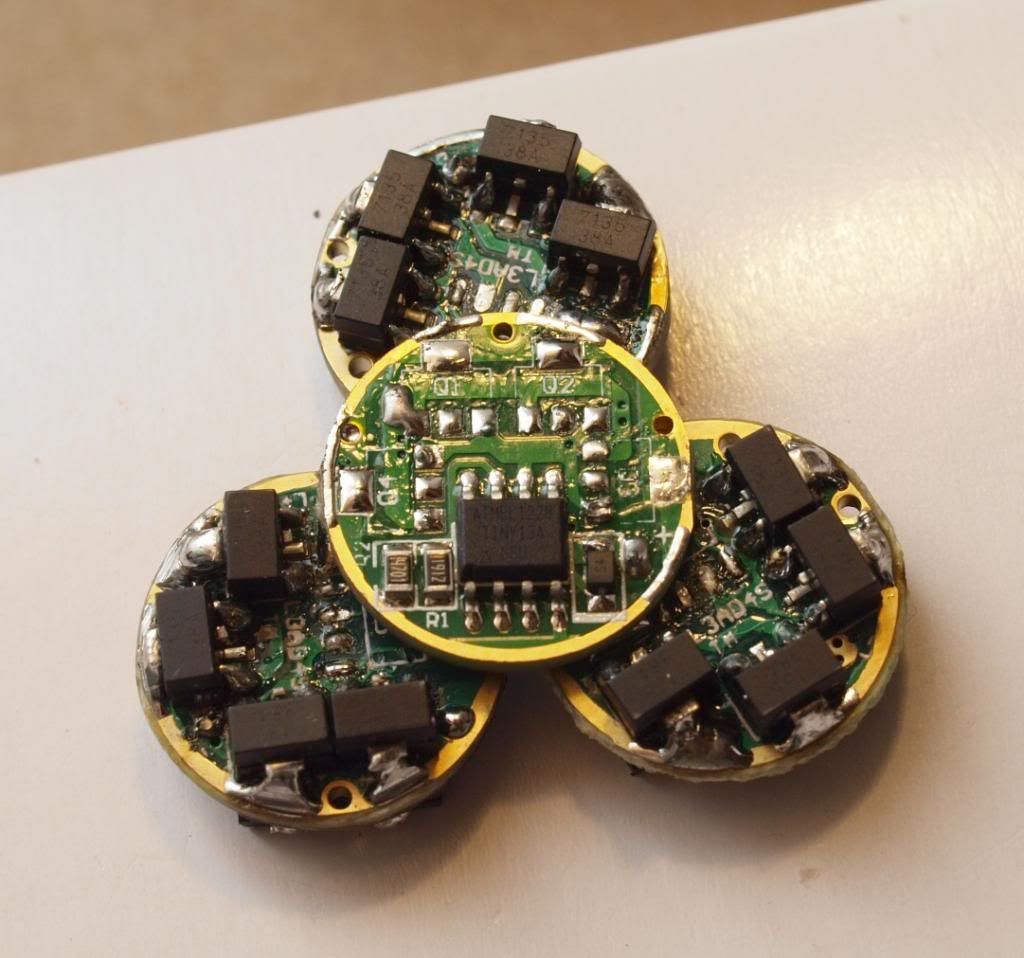
3x KD 7135v2 boards stripped of everything but the 7135s and stacked. A total of 16x 0.380A chips on each board to deliver 6.08Amps regulated to each emitter.
Didn’t I say I would aim for 5A per emitter?…well… yeah, but sixteen chips is a much rounder number… :bigsmile:
These will be controlled by a single master board, a stripped Nanjg 105c with an Atmel MCU running some custom firmware and Zener modded for 2S input power.
This is the general layout of how I plan to mount the driver setup into the flashlight cavity.
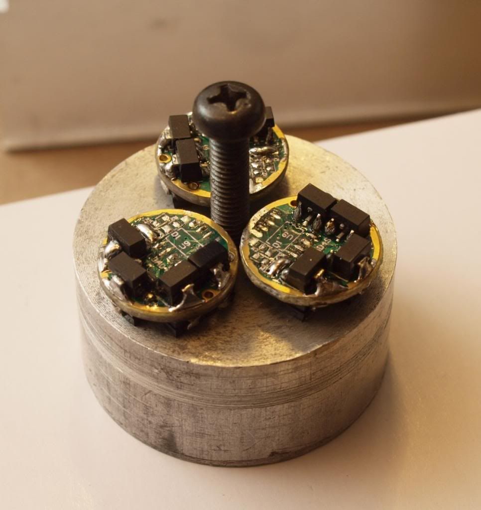
Still need to work out the specifics but I may use this aluminium slug and drill some 17mm recesses into it to snuggly fit the slave drivers. Have it act as both a heatsink for the 7135s and a holder. The master will probably be mounted more loosely near the contact board, that way I can easily get it out and reprogram it if needed.
The bolt is a longer replacement for the one that usually holds the reflector down (standard M5 bolt from what I can tell). Just playing with ideas at the moment, there’s so much driver cavity space in this light that pretty much anything is possible. Trickiest part will be to route the 3 pairs of emitter wires through it all neatly and out to the emitters. Might be time to do some 3D mockups again.
Cheers
Linus
This is just… wow.
WOW alright.
Thanks guys, still so much to do ![]()
That is not a microcontroller, that is a serial EEPROM.
Ah too bad, so I guess the other generic chip is the controller?
Yeap that must be it.
i hope you are taking notes on this build
because when you are done ill be sending you a valuable sum in dollars to build me one ![]()
Hehe, I do have a spreadsheet of all the parts costs but I’m afraid to total it up for fear of what I’ll see! … ![]() :money_mouth_face:
:money_mouth_face:
Just hoping the final light will be worth it ![]()
Tested the driver circuits today. Zener modded MCU board is doing it’s thing and the individual 7135 slaves are supplying the expected 6Amps to an MT-G2. This thing is dangerously bright at that output level, hence the welding glass ![]()
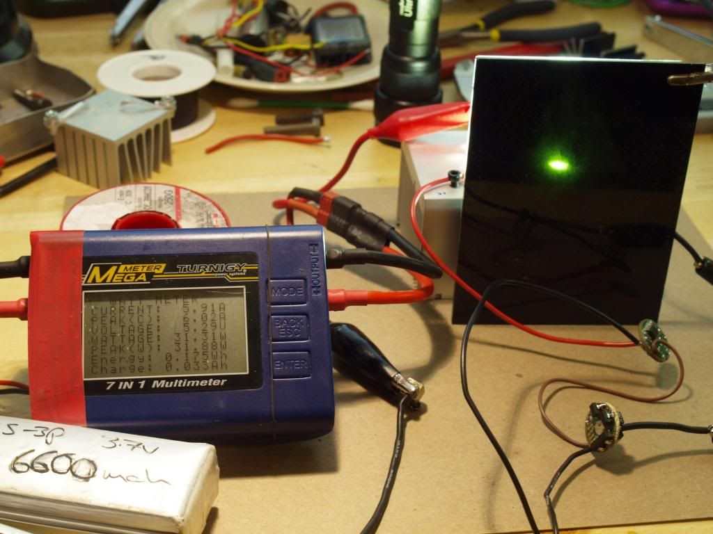
Lipos already slightly down after a bunch of testing, also crappy long test leads not helping hence the 5.9A on the readout. Started out stable at 6.02A.
At that drive current I measured 6.9v across the emitter so that is matching up perfectly with the graphs I was looking at. Should be resulting in well over 3000 emitter lumens too. :bigsmile:
-
Keeping an eye on the temperature of the 7135 board I didn’t notice anything too alarming running for 30s or so on high.
If my calculations are correct, on a fresh lipo input voltage of 8.4v, dropping to 7.6v once it gets to the driver and combined with this measured vF of 6.9v @ 6Amps, each 7135 driver board should “only” have to dissipate around 4.2Watts of heat.
This should be manageable and with deteriorating input voltage over time this will come down gradually from there.
In any case a little bit of heatsinking and I expect these boards should be quite happy running at these drive levels, that is until the massive amount of heat coming from the emitters overwhelms the whole situation anyway! ![]()
This is getting really fun now! ![]()
—
Edit: Don’t pay any attention to the Voltage or Wattage/Power readouts on the meter, the voltage reading on that unit has been broken since basically day one and as a result the power rating is also off considerably. Current reading is thankfully still bang on and very useful ![]()
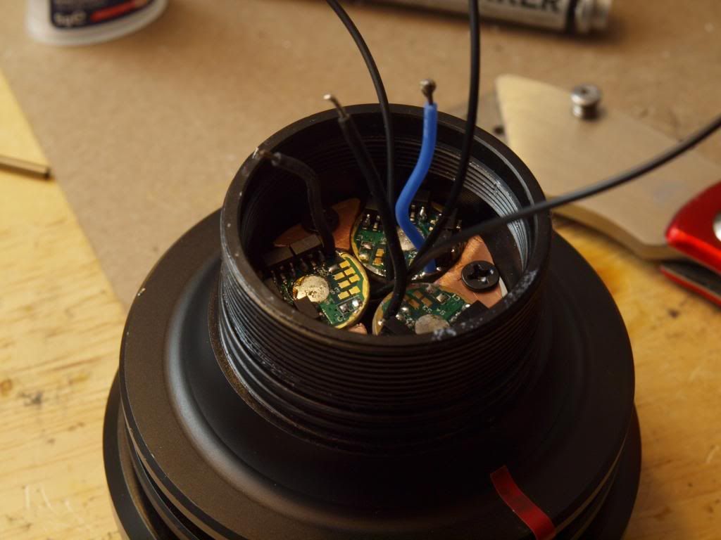
Ok, some progress on the driver mount/heatsink.
I found an aluminium piece from an old school project that was exactly what I was looking for. I ground the OD down a bit so it would fit nicely into the driver cavity,
drilled 3 holes through the edge for the LED - wires and heavilly countersunk the center so the reflector retaining bolt could sit inside the piece neatly below the drivers. I should still be able to get my allen key in between the driver boards to the tighten/loosen the reflector bolt. It’s a bit messy right now with all the excess wiring but it should work ok.
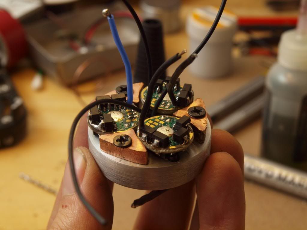
The copper pedestals/retainers I made out of some of those copper tabs I had ordered for creating the thermal path between the emitter plate and the reflector. I reflowed them together and cut and filed them down to act as retainers for the boards. The top of each copper pedestal is flush with the driver board ground ring so I will solder some connecting tabs between the pedestal tops and the ground rings. This should hold the boards securely in place, act as the primary heatsink path for the 7135s and also supply battery negative/ground for all the drivers.
To get battery negative to the pedestals I’ll probably solder some relatively fat supply wires directly to them.
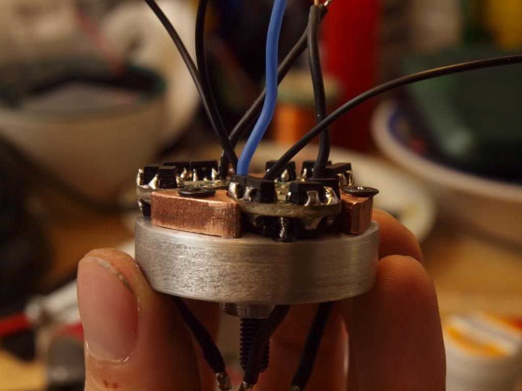
For the positive side of the circuit I’ll just run a single fat wire from the contact board through a hole in this driver board holder (which I still need to drill) and split it from there to the individual leds.
I have a little standoff on the bottom of the driver mounting assembly that will give me enough cavity space between it and the emitter plate to route the individual LED supply wires.
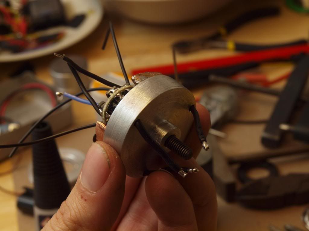
Here is the whole thing dropped into the driver cavity. It’s sitting considerably higher here than it will end up because the LED - wires are in the way. Haven’t drilled the led wire holes into the emitter plate yet.
Annoyingly once I had everything test assembled an LED - cable broke off and took the solder tab off one of the driver boards. So I need to fix that, those KD 7135 boards are a bit crappy and weak in that regard I’ve found. Similar thing happened on my Apex build, maybe I should have just sacrificed a few Nanjg 105s to build these slaves…
So that’s it for now.
Next I’ll look at the battery carrier modifications to deliver power from the XLR power input to the driver section. I won’t be attempting to make it 18650 compatible at this stage so that should be relatively straight forward. No way I’d get it all finished before the end of modvember otherwise! ![]()
Cheers
Linus