I am hoping this can turn in to a sort of ‘How To’ type thread for people who go looking because I had a bit of a search and found a few threads around with some info in them but a dedicated thread on how this is done would be helpful.
So this is something that I want to have a go at. Stacking the 7135 chips is fine, I have done that before, but I want to check what is done before that and what exactly this mod allows me to do? I.e. Run two 18650s or 18350s? Only power an MT-G2? etc.
Good questions Tim. If you can stack 7135 chips then you can do this mod, no problem!
You can use this to power a 6V MT-G2 with two cells in series, that's it! Basically the 7135s don't care (within limits) what the overall voltage is going through them, but rather the difference in voltage between the input and output side needed to regulate the current output (depends on LED vF) The MCU, however, does care what voltage is put through it so all this mod does is keep the voltage feeding the MCU at a safe level. That was overly simplified but I think that basically it is true. What this mod does not do is turn the 105C into a buck or boost driver. Input voltage still has to closely match output voltage.
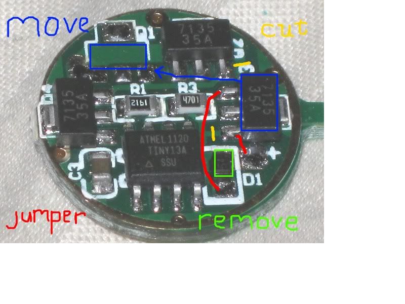
The 200 ohm SMD resistor goes in place of the polarity protection diode on the MCU side of the driver. It's function is to limit the current that the zener diode has to burn off.
The 4.3V zener diode goes on top of (if you have a small SMD or similar package zener) or otherwise in line (if you are using the bigger diodes like you have shown) with the input capacitor on the spring side of the driver. It basically burns off excess voltage as heat so that the MCU doesn't get fried (IIRC it is rated for up to 6V but is happier around 4.3V). The polarity of this diode is important. You want the diode line facing away from the ground ring. If you are using one of the bigger diodes you can use the first star to make one of the connections. I prefer to use to smaller diodes but really as long as you can hook it up, it should work.
There are many on here that are much more knowledgeable than I am when it comes to these things, but I've done quite a few now and they all have worked so far (knock on wood!)
Here you can see the small diode on top of the capacitor:
On the other side you can see that the diode has been removed and an 0803 200 ohm SMD resistor soldered in it's place
These are the parts I use:
4.3v 0.5w Zener Diode in a SOD-123 package data sheet
200 ohm 0803 SMD resistor
Those Zener diodes look right to me. Those resistors might work but they also might be a little longer than what is ideal. Search for some 0803 200 ohm resistors, those linked are 1206 (this is the external size).
Looking at the first picture above. It appears that the new diode is placed parallel to the stock capacitor. If I understand right, the cap is between Bat + (via new resister added) and Ground. So is the diode just letting 4.3 (or whatever plus it's own consumption) volts continuously go to ground?
The diode bleeds off anything higher than 4.3v, or whatever you use for a diode, (I use 4.5v). It just keeps the MCU from seeing the higher voltage. The 7135 chips still see the higher voltage and that is why they get very hot, very fast.
After doing many of these, I feel that the 7135 chips need heat sinking to keep them from getting too hot and dropping out. As to the best way to heat sink them? I do not know. Fujik isn't enough. It needs to be something like direct to metal, so I use copper and it seems to help, as the light does not dim near as quickly. When I say quickly, I mean that with no heat sinking, pushing the MT-G2 to 9 amps, causes dimming in seconds, where with copper soldered to the outside tabs of the 7135 chips, it lasts for a couple minutes before dimming.
Thanks O-L. Seems like it could drain the cells down to 2.25v each if you let the light sit too long. Also seems a bit inefficient. I think I like Rufusbduck's idea with the L78L05 regulator better. I'm probably missing something obvious here though.
I don't think you're missing too much! This is not the optimum solution, it is one that was designed to work with existing drivers and still be able to fit into lights with small 17mm driver compartments. With IMR 18350 cells I haven't seen much any thermal throttling when driving an MT-G2 at around 4.5A when actually installed in a host. With two 20Rs sitting in the open air you see the 7135s begin to thermally regulate (cut current) at less than 30 seconds. The closer the input voltage is to output voltage (look to emitter vF curve) the less heat the 7135s will have to shed, this means that batteries with a little more voltage sag may actually be better for this setup.
Hi RMM. I just realized my post may have come across a criticism of one of your products. Just wanted you to know it was not intended as such. I think it is a good product and I could see me using it in some of my lights. I was talking more to myself for a particular application. Thank you for taking the time to respond.
If you have any doubts on what parts to get for the zener diode mod, you might want to buy RMM’s zener diode mod kit. His kit includes all the parts you need to modify the 105c, plus 3 pages of excellently written instructions with color pictures.
Maybe, but cutting traces and all that is not necessary. Seems like it would be pretty easy to stand the regulator on its side with the "+ In" laying on the input pad for stock diode, then a short wire to the ground ring and a short wire for the MCU feed pad. Solder wires and trim off excess.
I am not well versed on electronics. That said, I did not heat sink the chips on my Qlite board that is running the MT-G2 in my M8 with Bucks copper pill and it holds output very well at 6.77A. With a start otf reading of 3564 lumens it drops to 3260 in 30 seconds as the 20Rs take the load, then over the course of the next 2 1/2 minutes it drops to 2953 lumens. At this point the cells are down under 3.9V and there’s heat throughout the pill and into the top cell (114º on the bottom of the head). This is, of course, head down and in stagnant air while in the lightbox. A very respectful performance I think. At 4 minutes, the heat is up to 144º on the lower portion of the head where the copper screws in, still making 2856 lumens.
As a direct comparison, with a sliced-n-diced MT-G2 in the OEM pill with 1/2” of copper added inside the pill, the start value at 5.61A is 2424 lumens with a drop to 1870 at 30 seconds and showing 1308 lumens at the 3 minute mark. So without the 8 ounce copper heat sink there’s more than 1100 lumens lost at a lower current. With the aluminum pill and that chunk of copper showing 1276 lumens at 4 minutes, the head is 132º.
Is the loss due to the regulation chips or the emitter itself heating up? With Bucks copper pill I have 18 total chips on the Qlite.
I have no idea how to isolate the chips from the mass that’s absorbing heat from that huge emitter, but even with 8 ounces of copper and exposed fins the heat builds up pretty fast, obviously. So I guess it’s a moot point whether it’s the chips or the battery sag or the emitter suffering from it’s own irradiation…
It’s also been pointed out to me that the fewer chips on the board the more each chip has to dump in terms of the excess voltage so they’ll get much hotter trying to run “sane” levels than otherwise. In the case above, there’s 18 chips dissipating that ~2+ V. Reduce that to the 8 chips that are native on the Qlite and it’s quite a different story…
I think that the even bigger thing with adding more chips with the MT-G2 (same principle for 3V LEDs, but way less heat) is that even though they spread the load I think that the battery sags more which helps out the situation a lot. Oldlumens' idea of using copper to suck away the heat is probably the best I've seen, although it isn't needed in every situation.
Since the chips are in parallel the extra 2 volts go to each chip whether there is one or twenty-one. The difference is the higher Vf of the led at higher current and greater voltage sag in the battery both lead to a smaller excess voltage burned off by each chip. I think you’re right otherwise Dale, it seems very common for drivers to ramp down due to heat from the led(s) rather than from the chips.
Lol, I’ve had it explained various ways so of course none of it makes sense. There’s a value of 2V. There’s 20 chips, the 20 chips dissipate that single 2V value handling a tiny bit each. They don’t all handle 2V. That’s one way I’ve heard it said, from an Engineer. At any rate, they do all handle the heat that dumping 2V generates, so each one has less heat to deal with from the scrub, but not from the emitter, which toasts everything in the end anyway.
The driver doesn’t “step down” as you put it. The chips fall out of regulation due to less available current from the cells. The chips can only allow what current is available to flow, not a driver control issue as much as available supply.
One thing I do know. Take the light off the meters and boxes and measurement devices of all kinds and take it outside to use it and you don’t perceive those losses until the cells are waaaay down! The lightbox might say it’s dropping like a rock in a spring fed pond but in use you just don’t see that. So I guess for all but the taskmasters it becomes a moot point. We do, after all, (or at least I do) make these to scatter darkness so we can accomplish a task. Whether that be checking for a loose wire under the dash of the car or making daylight at 2AM to help you decide which varmint to shoot, they all have their purpose.
I’ve thought about getting rid of some, more than 30 is just too many lights. But which ones? lol I like most all of em each for a different reason, and have a couple more on the way even now. Oh well, time to build a cabinet…


 ! My T10B MT-G2 build came out real nice using Richard's kit.