This'd provide an alternate current path than through your button switch.
Something like this Omron 12VDC 16A. The current loss for the relay is a lot less than what you'd lose through the long thin wires of your coil if you were to direct current that switch.
Yeah it’s more a set and forget type of thing, but you’re right the last thing I’d want is to worry about damaging something when doing maintenance or tweaking the driver.
It’s another reason why I felt I had to maintain the twisty interface to the driver though, so I can easily get to the components in the head and not have to worry about desoldering the main supply wires each time.
With regard to the contact surfaces wearing away on the contact board, the positive contact is basically a brass cylinder to a brass cylinder so that won’t really wear and the neg contacts are rounded solder + copper wire pressed against mostly the aluminium of the contact board holder itself, and only partially to the contact board edges.
If the board wears down much more than it has up to this point I’d be very surprised, but even if it wears away the ground ring on the board it’s not a problem.
I’m more concerned about the area around the positive contact point wearing down and opening up till it no longer functions as a registration and centering socket. It’s already a bit rounded from my earlier botched attempts are alignment and spacing.
Are you talking about the coil for the reed switch? I didn’t think I would need that much current to generate the magnetic field for close range operation!?
Or do you mean for providing power to the drivers/led?
If that’s the case, no current powering the leds will go anywhere other than directly from the battery pack through those contact posts and into the led and linear driver circuit. Batt+ goes directly to the emitter + from the contact board and batt /ground goes to the ground pin/ring on the 7135 slave boards which in turn connect to the emitter.
The only thing that the trigger clicky will be doing is providing power to the Atmel master board so it can turn the 7135s on and off as required. Those will then switch and regulate the <18A to the emitters directly.
But for that to work I need to tap off a positive source from the carrier, run it out to the trigger clicky switch and back (through the coiled wire you can see) then somehow bring that circuit back to the mcu which will be housed in the head, that’s why I need to go through a third contact interface in the contact board.
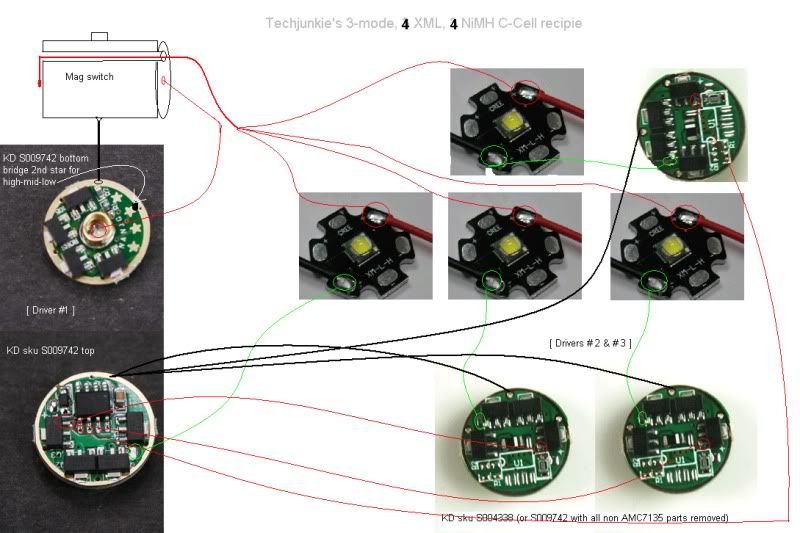
For clarity on the driver/emitter side I’m basically doing exactly this…
OR
I could keep the two circuits separate, one inside the head tacking battery positive from the center contact point and feed it through a reed switch to power the mcu, and a second circuit in the carrier with an electromagnetic coil connected to the carrier sources and switched by the trigger clicky. Then, in my mind at least, when the trigger clicky is active it generates a magnetic field in the coil which turns the reed switch on in the head and powers the mcu on, click it off and everything shuts off again.
With this I wouldn’t have to worry about having a third direct contact point on the interface but I’m not sure what kind of reed switch and coil combination would work for this type of thing. What kind of range I can switch over and so on…or indeed if this is feasible/sensible at all.
Do you have any experience with reed switches and electromagnetic coils? Would really help me out
It was just a thought since I wasn’t relishing the idea of going in and sanding down that copper contact disk and making that approach work…
Love that video; “You cannot be awesome without this rifle”
Back to the thread, Hold Sweet Mother of God, now that is a Shocker! Mine is relegated to a box in the corner as of late. I still like it, but I have other lights that get more use due to form-factor.
Hehe… not surprised by that, the shocker is a club of a light.
Thanks for ressurecting the thread and giving me a kick to get back to this project, got a bit distracted over the holidays with simpler mods.
Time to finish this one off and finally see it throw some photons!
ps. Oh and I found a pair of these motherboard auxiliary blowers a while back and am thinking of making a bracket for them that can be attached to the BTU so they can blow some air over those heatsink fins. They’re just the right width and it looks kinda cool with a pair of these blowers hanging off each side of the light.
Don’t know how much it would actually help to keep things cooler but they do move a decent amount of air even at ~8v. Worth giving it a go anyway i think.
Hi guys, sorry for the delay.
I definitely intend to get this sucker finished but have been getting sidetracked on other projects lately. Definitely need to get the ball rolling again so I’ll try to make some progress this week, thanks for the kick
Sounds good. Thanks for the update! Been following this one for a while.
I know what you mean about being sidetracked... I have been working on my own BTU shocker since November...and it is just a simple mod in comparison to this!
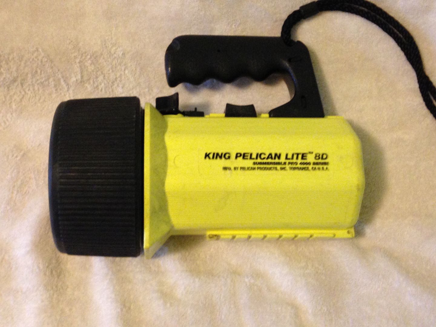
I did a mod on a Pelican King D a while back that included a rail mounted reed switch for mode control of a Hipflex driver that might give you an idea or two. I never got around to taking pics of the build since I don’t ever use the beast as the buoyancy is all wrong. In any case a reed switch is capable of operating the mcu all by itself. I’ll take some pics and post them in a bit.
At the front is an odd shaped lever that controls a dpdt switch and allows the Hipflex driver to control either 4 mce’s or 3 x 3p xre’s. Behind that is a lock.
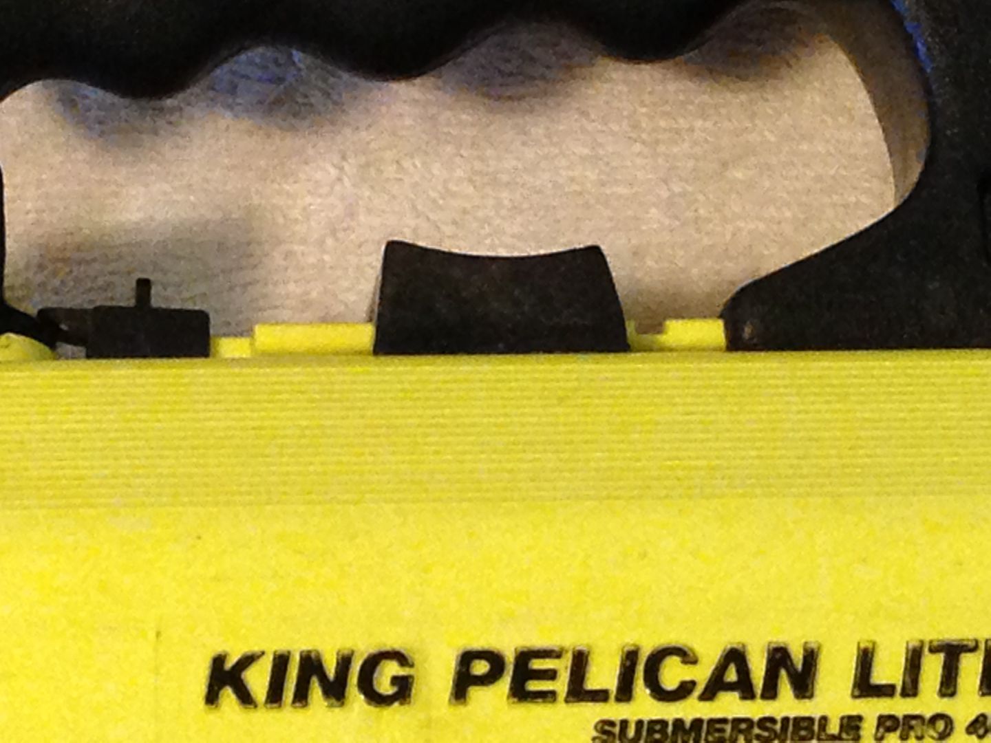
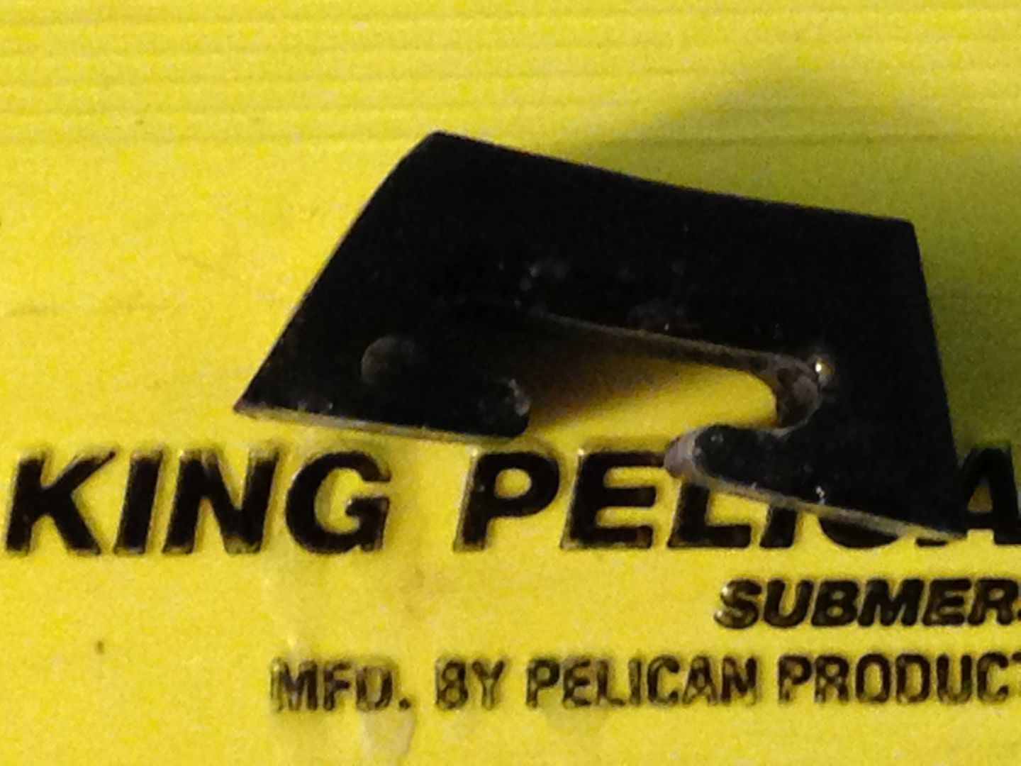
The magnet for the reed switch is located in the black trapezoid just in front of the handle. It’s made from fiberglass cloth and cast epoxy resin and tinted with shoe polish.
You can just make out the magnet at the left.
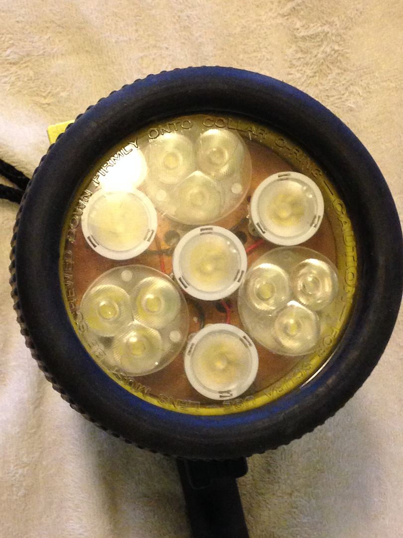
The business end.
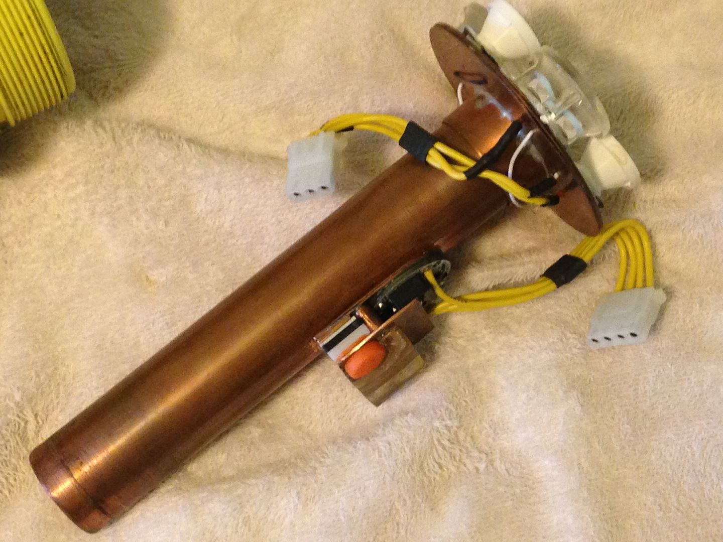
This how I manage heat in a plastic housing, 1 1/2” copper pipe with a portion of pipe cap attached to the 3-layer copper base plate. On the side of the tube is the driver, the reed switch cast in epoxy, and a momentary switch for programming.
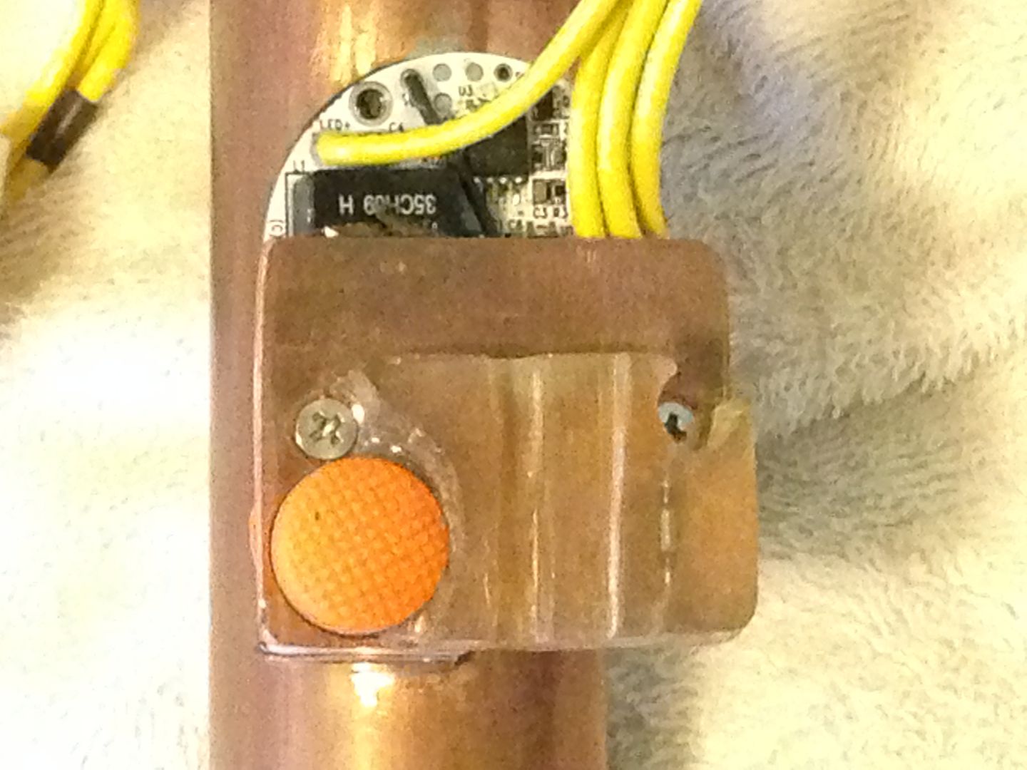
A close up of the reed switch located below the right hand screw. The epoxy is fitted to one of the interior ribs of the host to keep it aligned with the magnet.
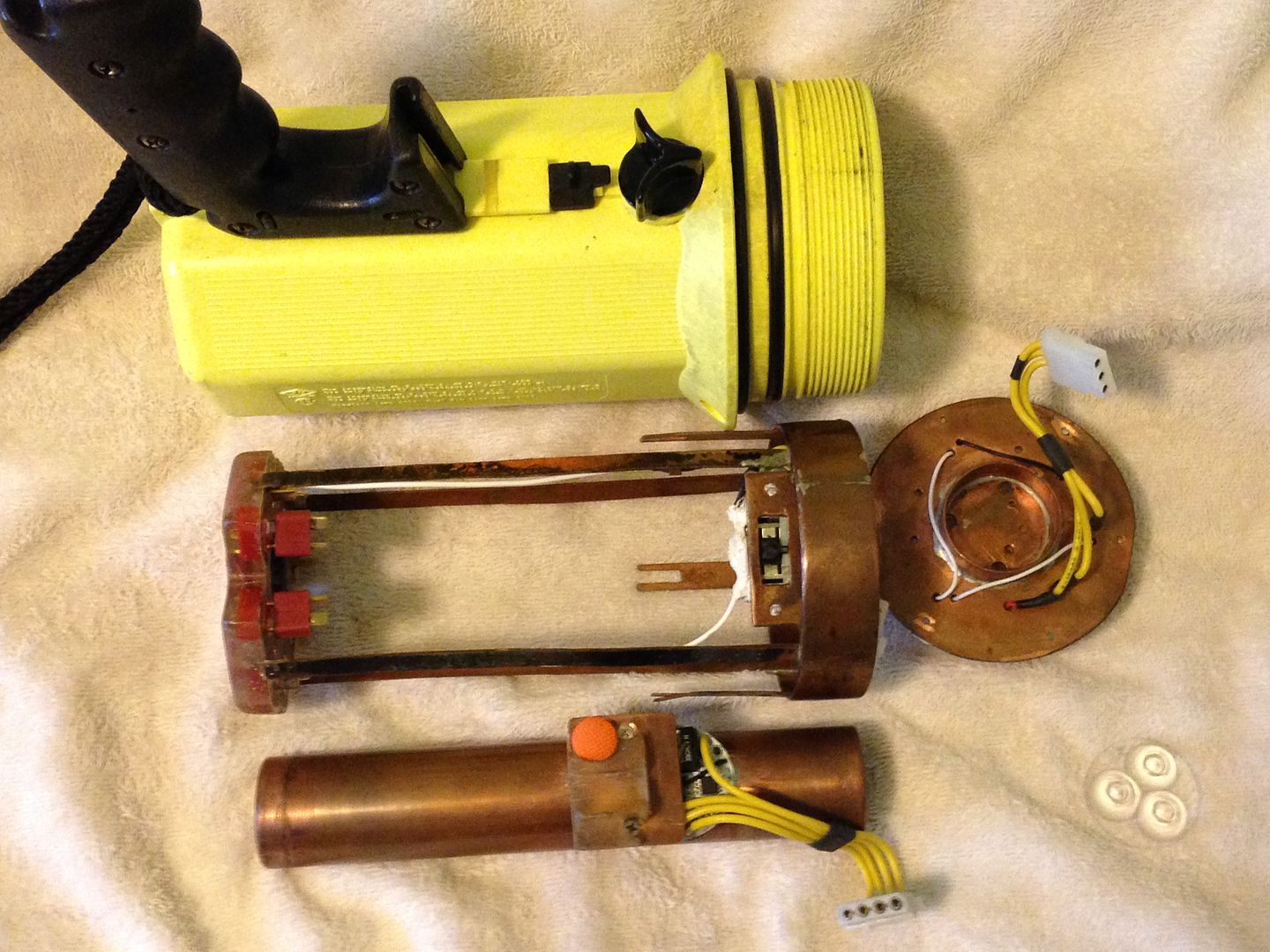
The rest of it is a cage to hold the dpdt switch, 8 male Deans connectors for the 30 4/5 subc cells, and the bottom end of the copper tube.
Lastly, here it is with some of the packs installed. There were two - 5 cell sticks, 4 - 4 cell sticks, and 2 - 2 cell sticks in a 15s 2p arrangement. I canabalized the 2 cell sticks for bike light packs.
The handle on your shocker reminded me of this light along with your question about reed switches. If you wish I can dump this post into its own thread and just create a link to it. This wasn’t meant to be a hijacking but it’s a big light with a lot going on.
Thanks for posting, very cool light you have there.
That seems to be the sensible way to use a reed switch, with an actual permanent magnet for activation. I came to the conclusion that trying to do an electro-magnet activated reed over the distances I would need wasn’t going to be a great idea or very efficient so I decided to go back to just doing a spring loaded contact to get the trigger switch line into the head.
Wow it’s been a while since I’ve been on here but it’s definitely time now to get this project finished.
I’m sure you guys know the feeling when you have 10 or so aspects of a project that all need attention and non are obvious or simple to knock off the list first. It’s easy to get sidetracked.
In any case I’ve now got two of those critical parts working. Namely the clicky switch circuit that passes power into the driver cavity through the contact board and the layout of the main power circuitry on the driver assembly itself.
—
First is the turning contact for the clicky switch. I just needed a raised contact patch that would complete the circuit between the switch wiring in the handle and the MCU in the head. That was easier said than done since it needed to be isolated from the grounded contact board and make contact only with the pin on the battery carrier when the body of the light is fully tightened down. Was fiddly to get the height and location of the copper patch tuned in but thankfully once I had it in the sweet spot it worked as planned.
It’s just a small piece of copper center punched to create the raised contact area, then insulated from the plate below with some kapton tape. Behind is a small hole through the aluminium with the wire to the MCU passing through it, the whole thing is then epoxied into place.
…and here is an old photo showing the spring loaded pin on the “battery carrier” that makes up the other half of the system.
Next I had to tackle getting the main power to the driver board. The positive will run directly to the LEDs so I cut a slot out of the driver assembly to accomodate the wire and for the ground I mounted a copper standoff to one of the driver posts. The whole assembly is grounded and each drivers outer ground ring soldered directly to the copper posts to make a solid contact. It’s really messy stuff so don’t look too closely, but hopefully it will be functional. The small red wires are PWM signal wires for each driver.
So that’s it for now but hopefully with the ball rolling again I’ll be making plenty of progress over the next few weeks. Next up is torture testing the whole power system wiring at full power (~18Amps) to make sure nothing melts or shorts out, fingers crossed.
Looking good. What are you going to do with the excess heat? May I suggest running a small power plant to supply electricity to a large town. Whats the eta for night shots? No pressure or anything.
