Welcome everyone! Greetings from Poland ![]()
I would like to present extended driver according to my personal project. Basically, I have to mention I am not an advocate of complex things, which nature should be simple and intuitive. From my experience I have concluded it is better to force a user to adopt certain regulations, which they will accept as theirs with time, instead of adding a handful of clicks just that one person has what they want. Let’s move into details now.
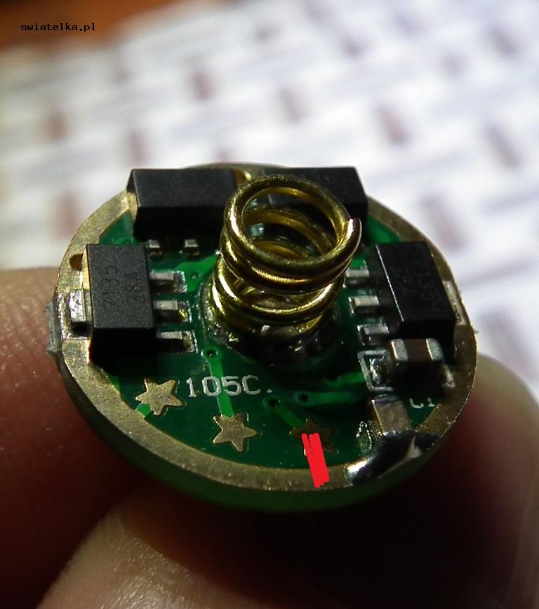
The heart of the driver is a microcontroller of the Atmels family AVR a – Attiny25V. High-speed PWM (lack of low mode flicker). Multiclick driver uses a ceramic capasitor, which is used to avoid the continuous “grinding” of EEPROM, which as we know has its limits – breached by a few;)). It has 4 programmable modes among the palette of 11types of brightness available in programming procedure. Factory settings are as follows: 2, 5, 8, 11 (0,15; 10; 32; 100).
Navigating between modes works two-way. One click makes you move to another mode in the loop, double click takes you back to the previous one. It allows us to; for instance, reduce brightness without clicking through stronger modes in the loop. After reaching the verge of the loop, moving further will cause „a jump” to the next verge of the loop.
The ceramic capacitor is used as one binary digit memory with a limited time of holding information. It is used to differentiate short loss of power supply voltage (click) from switching off. Standard capacitor 470nF secures time, after which power supply loss is off for about 0,5 sek. Capasitor change to 1 µF allows the time extension (the length of a click) to 1 second. Hence every loss of power supply shorter than 0,5 second is treated as “a click”, each subsequent click after shining shorter than 0,5 second is treated as the next click of a multiclick.
The programming procedure of a given mode is elicited by 6-click, while being in the mode we wish to change. Displaying the sequence occurs in the lowest mode (signaled by one twinkle) upwards. Every mode displays for about 1,5 of a second. After reaching 100% there’s one twinkle, then it displays modes downwards. The mode is programmed during the display invoked by a click or by the mechanism of turning off the switcher. If we cease to do anything during the procedure of presenting modes upwards and downwards, the light brightness will remain as previously set.
Brightness level palette available in the programming process:
0,02%
0,15%
1%
4%
10%
18%
25%
32%
50%
70%
100%
Stroboscope (The strobo) mode is invoked by 3-click. The intensity of the flashes is the same as in the mode we have invoked the stroboscope, and has an optimal frequency 2Hz.
Precise battery cell voltage measurement under full load is invoked by a 4-click. I have approached the subject in my own way, assuming the following:
Practical band of discharging the battery cell Li-Ion under load ranges from 4.0V to 3.0V. After invoking a 4-click, the lamp flashes for a short moment in 100, then the measurement happens. After that, with a number of flashes in 20 mode, the driver informs us about one tenth of V by 3.X. For example 8 flashes indicate the voltage of 3,8V; 5 flashes mean 3,5V, etc. The range is from 0-10 where 10 indicates 4.0V (the battery cell just unplugged from the charger), while no flash (3.0V) means that in a moment you will be receiving a low voltage level warning. This way of measuring proves correct in diagnosing new lamps and an associated drop of voltage in the whole construction (a contact quality, etc.), since we are given the information which physical voltage is found on the driver level.
Temperature monitoring
This procedure always works in the background and monitors current driver temperature. It is based on a processor internal temperature sensor 25V. After reaching safety threshold (default 60C) the driver flawlessly reduces power, then tries to equalize to the set work mode. If the heat isn’t effectively absorbed, next reduction occurs while holding to the preset safety threshold. After cooling the lamp (for instance, cool air blow around the lamp case) the face value returns for the programmed mode. This mechanism is efficient enough, so that we could even wrap the running lamp in a blanket without any fear of damaging the equipment… or the blanket ;-).
Since the range of tolerance for sensors of the processors within the Attiny 25/45/85 family is rather high, the Procedure of Service Regulation of Temperature for Safety Threshold (default 60C) has been implemented. It also allows advanced users for tuning the driver so it would fit the construction it works in.
10-click – the temperature limit extended 5C upwards, confirmed by 3 flashes.
12-click – the temperature limit extended 5C downwards, confirmed by 2 flashes.
The above changes can be done repeatedly, e.g. 10-click performed twice in a row will rise the temperature by 10C (3x =15C etc.), just as 12-click tunes the mechanism to our needs.
Auto-calibration of temperature safety treshold invoked by 9-click (when assembled in flashlight: driver start in 100% mode, lamps head getting warm, then by touch, when sense max. safe temperature, by any click this “touched temperature” is written as a max. temperature treshold).
RESET to factory settings (modes to: 0,15; 10; 32; 100 and temperature for a safety threshold back to 60*C). Inovoked by 8-click.
The low battery cell voltage warning starts when the cell, in a working mode reaches about 2,9-3,0V. Then a single flash appears and a reduction to another, lower level from the programmable modes palette (we reach ~2,9V in the given mode, and after a flash, we drop to another, lower mode). This works to the level 3 (1). When this happens the lamp will retain this level, flashing periodically every 10 seconds. After reaching 2,8V you will experience the last mode reduction to 2 (0,15). After reaching critically low voltage 2,6V, the driver 4 flashes and goes into sleep mode.
According to my guidelines, my friend Pyra is the codemaker of this project. By the way, please visit our flashlight forum: www.swiatelka.pl
The driver is available in two versions, 3,04A based on 8-pack AMC7135 BIN 380 mA and a standard 2,8A on AMC 350mA. The drivers on offer will have soldered wires 0,35mm2 in silicone insulation (model type, current of continuous operation - 10A). Upon request (without any additional payment) they can have a soldered metal plate of the Omten PBS101C switcher (this switch has a 5mV voltage drop@5A and plates made of coated bronze), where the spring with a positive terminal connects to the cell. This increases the surface area of contact between the driver and the cell, by reducing voltage drop all in this place. I believe it is better material than the usual, brass disk.