When I said the same thing a while back I was corrected by HKJ - well, not exactly corrected, I just got a simple "No." and no explanation (yes, it was actually both bold AND red in the original). So I wish I could now give the correct explanation, but I still don't know where I got it wrong.
The power consumed is divided because the current is divided but the voltage drop is the same for each chip on a given driver.
Well I was just guilty of imprecise wording. When I/we say 'burn off the excess voltage' it's not actually burning off voltage, it's just a way to make it understandable by us non-propellerheads. Of course the voltage is the same everywhere because they're all in parallel but the amount of current each chip has to handle in order to get Vin down to the required Vout is less per chip when there are more chips in the circuit. Which is just about the clumsiest thing I think I have ever written, so I think I'll stick with 'burn off the excess voltage' to preserve my own sanity.
Maybe this diagram will clear things up...

It’s one of those “once you understand it” things you go “DOH!” and slap your forehead. PilotPtk and Texaspyro schooled me and though I’m no “A” student it’s pretty clear in a general sense what goes on. At lower drive currents the forward voltage of the MT-G2 is much lower and there is also much less voltage sag in the battery. These two combine to greatly increase the voltage drop forced on each chip so increasing the current changes the amount of excess voltage each chip sees.
Higher currents also lead to higher voltage drops at every other point in the circuit as well.
If you want to run the MT-G2 with a 3A driver just add a high wattage/low ohm resistor to lessen the load on the chips. To pick the right resistance value find the difference between the Vf at your drive current and Vb with depleted cells. Just for kicks I’ll pick some random numbers:
Vf= 4.5V @ 3A
Vb= 5.5V depleted
So 5.5-4.5 = 1V
3A x (?) = 1V, answer = 1/3 ohm.
In this example, no matter what the battery voltage is, at 3A 1V will drop across the resistor and the rest across the chips. A higher value resistor will lessen the load on the chips but raise the “depleted” voltage at which point the chips fall out of regulation.
So, would it be more efficient in the Zener modded lights to use Li-Po cells with their lower initial V? This would more closely match the Vf of the emitter and not have the waste scrubbed off by the regulation chips, right? And, don’t the Li-Po cells hold current better, with higher capacities?
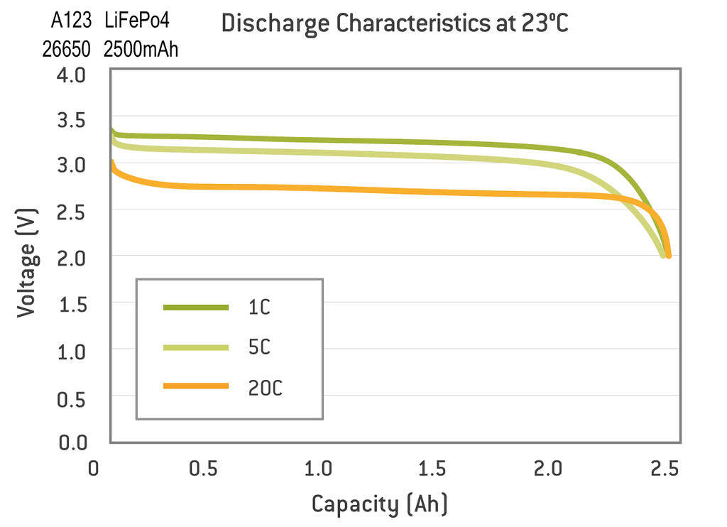
So, a LiFePo4 18650 cell like this one, with 3.2V nominal and 3.8V Max would have a potential 7.6V full charge and deliver 18A continuous current discharge, so would this be a better bet for a Zener modded light? Capacity is low, but not all that much lower than a 20R and if it holds it’s own it’d come out ahead, would it not?
If a 2 cell tube were made for the HD2010, couldn’t these A123 120A LiFePo4 cells be utilized? They have a charge rate of 10A, so they’d quick charge easily and deliver up to 70A continuous discharge at 2500mAh capacity with an MT-G2 in a 2 cell HD2010, would that be like a totally optimized light?
It would probably be more efficient at lower drive currents. As soon as you load most of the LiCo cells with 4.5+ amps though they tend to sag enough within a short period of time to bring the voltage difference between the input/output of the 7135s pretty close. For this reason Pana. 3400s, etc. might actually be better from an efficiency standpoint with the zener modded 105C. The closer Vin is to Vout the less heat the 7135s will generate.
CC, you crack me up.
So what happens when a driver is built up to make extra power but the cell being used cannot deliver that power level? Are the chips out of regulation in that scenario? ie: the driver is set up to make 6A, but the cells will only give 4.5A. (Setting it up to run on Samsung 20R cells then using Sanyo UR18650FJ cells) This is well below the total of the chips, in much the same was as the exemplary 5.5V is, but then, we’re talking Volts not Current, correct?
Oh to heck with it, I’ll just keep cramming screaming hot batteries in on top of drivers bristling with components until something smells bad.
Yep, then it would be "out of regulation" and would begin to dim as soon as the battery starts to lose voltage. Interestingly though, you may still have regulation on the lower mode levels. Even though they are pulsing full current the cells probably won't sag as much and may still stay in regulation for a while at the lower PWM levels (regulation meaning Vin > req. Vout).
According to this, this cell would hold 12A for an hour and a half all by itself. In a pair configuration running series it might last longer. And being as how we’re talking 5-8A, looks like it’d hold up pretty well.
Duh! :~ sorry bout that
That does look good. However, if we're stepping up to two 26650s we also can likely fit a more suitable driver, which then brings us back to a 4000mAh+ LiCo cell.
The larger drivers that everyone talks about have thermal shutdown that occurs entirely too fast. And as you know, I do not want the light telling me when it’s time to cut power in half. If I want to run it til it melts, then so be it. So that kind of driver is just aggravating. Ask MRsDNF. Or anyone else that’s used those big drivers to punch up the MT-G2.
I’m looking for an hour, hour and a half at 3000 lumens. Not 3 minutes.
At lower currents the lifepo4’s might well work out better but don’t get stuck looking at high drain cells in a low drain light. Remember how much better the Sanyo 14500 performs than the efest 14500 at 2A or less? Try and see the whole picture for each set up and put together the best combination.
If you are trying to drive at lower currents then choose a cell rated with the highest capacity at that current rather than a cell with lower capacity but higher amp rating you won’t use.
Yup, buy it and fry it.
I can’t think of anyone better qualified to run a series of tests to find the optimum balance between cell types and chip count. Let me know when to make a big batch of popcorn.
Only briefly would 2 cells be above 6.5 V and for 5A you need more than that. These would be perfect for 3A but I don’t think you would ever see 8A even with multiple parallel cells.
Are you going by charts or have you actually measured forward voltage of an MT-G2 at over 6A current draw?
Just the charts. That’s why I volunteered you to test this. :bigsmile: You have operational MT-G2’s running at high currents. What’s the voltage drop across the led. If its over 6.5V then you won’t see as much current using cells that don’t add up to that voltage.
Comfychair posted This graph which indicates ~3.5A at 6.5V. It doesn’t matter what the cells are rated for. If they don’t have the voltage they won’t supply the current. Those cells would still be a better fit for a 2.5-3A driver than liion just not for 5-8A.
Edit- graph data from Djozz.
The only thing I can find in my notes, at this point, is where I thoroughly tested the MT-G2 in my chopped AA MiniMag. On a pair of High Discharge 10250 cells and a stock Qlite (other than the Zener mod) it pulled 2.98A at the tail, with Low at .05A and a Vf of 4.89, Medium at .78A and a Vf of 5.30 and High at 2.98A and a Vf of 6.40. So, no, the LiFEPo4 cells would not be likely to run the MT-G2 the way I’m wanting it run, even with the consideration of the larger 26650 size.
I will be going the other direction soon, however, and test 2 26650 60A cells. They are en-route and should be available to me next week. Also have some 35A 18650’s coming at the same time. So I’ll be testing my theory about the higher capability cells cruising with the lower demands of even a fairly hard driven MT-G2 and ultimately I plan to make my M8 direct drive again with Bucks big copper pill and see how these new cells run it. The base I have is a pair of 20R’s running it at 12A. They didn’t fare well for very long at all.