Or maybe a blackbird with delusions of grandure.
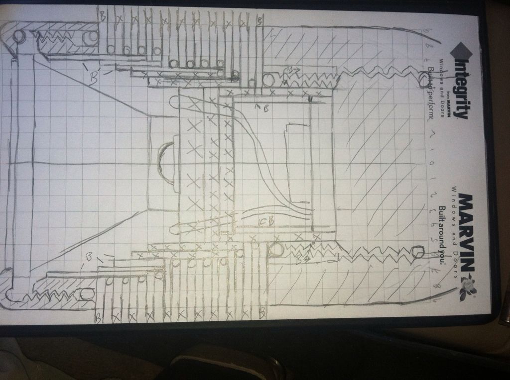
First sketch.
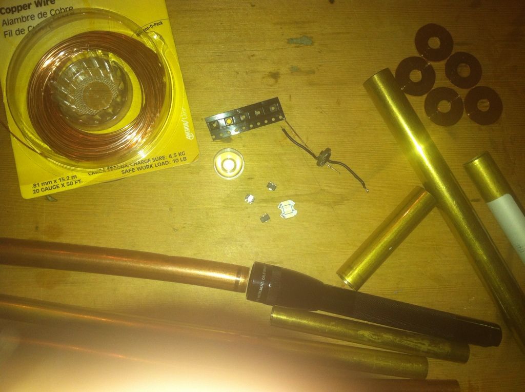
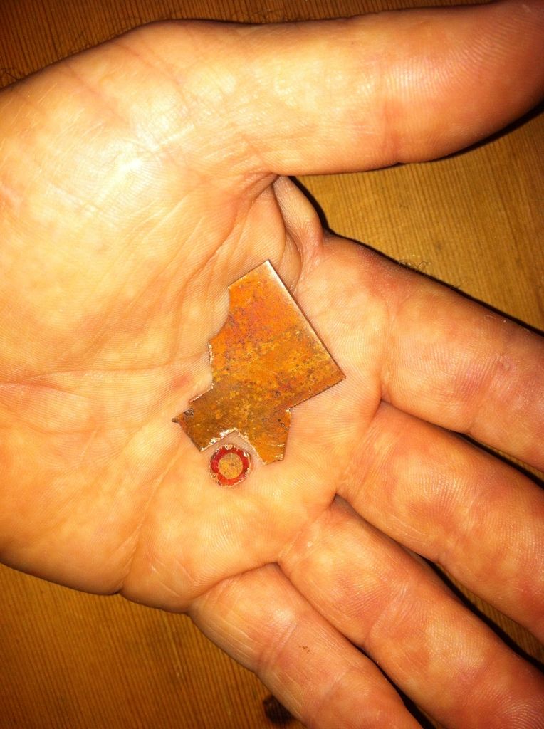
Some parts.
There are some corrections to be made but since there will be so many pieces going into this head I figured I’d better map it out a bit. Usually I just wing it.
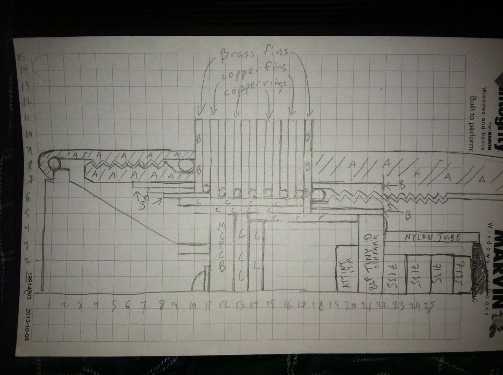
Second effort(well third actually but the second one you get to see). I’m not at home so the bezel might be off but this is as much as I’ll need to go on.
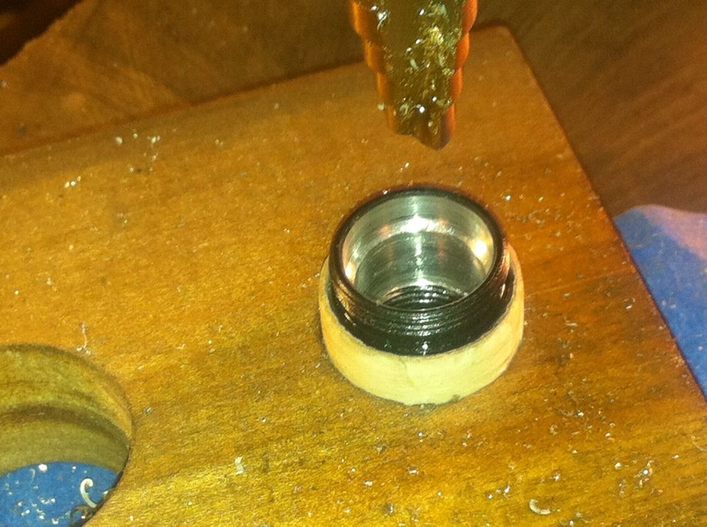
Here we go! I started today by wrapping up the head in masking tape and pressing it into a block so I could start the bore with a step drill. It does a nice job self centering but can’t drill all the way to depth.
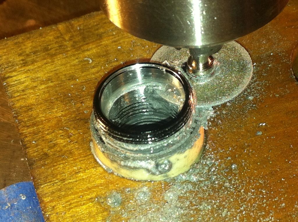
Then I put a dremel blade in the drill press and cut the bezel threads free while keeping the o-ring groove intact.
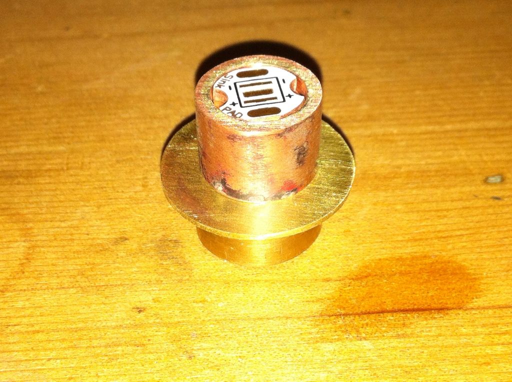
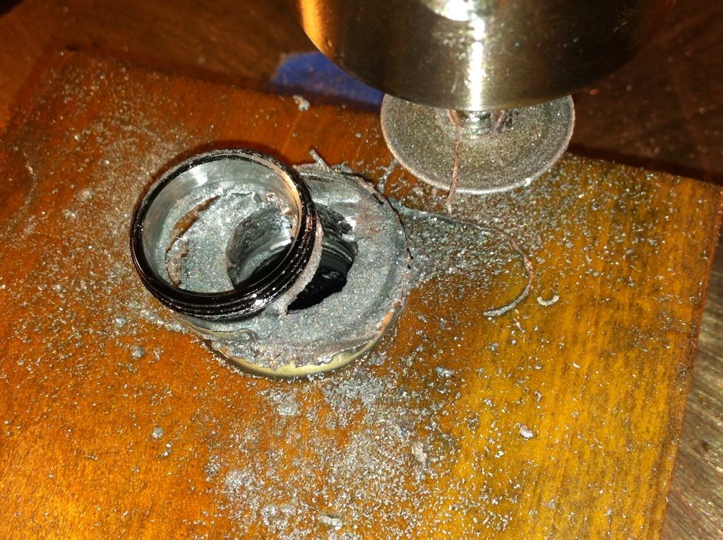
Success!
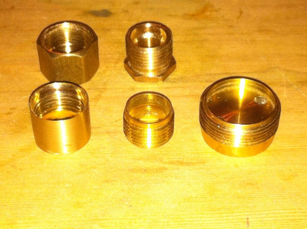
I set these aside for now and while I had the dremel blade installed I cut a 5/16” brass compression union in half, put one of the halves in the vise with the cap on and reamed it out from both ends again using the step drill. The inner piece was finished off with 200 grit taped to a drill bit and spun until it was the correct size. The outer piece(the compression cap), I ground the points off with the grinder then again snugged this part onto a 3/8” bolt and spun it first over a file and then over 200 grit. Lapping is not necessary for either of these. Here is how they look now with the other half of the union pieces in back and a p60 pill to the side.
Now I need to finish reaming out the head pieces. More tape, sandpaper, and spinning. I went through several layers of skin but got the bezel threads done.
But I still need to finish reaming the head so the outer brass part fits.
Time to go to sleep and grow some more skin.
Here is a pic of the head with the tools I used to finish the bore. The bit on the left was used in the dremel to keep the bottom of the bore square and the variable Dia sanding drum on the right removed the rest of the material. Took about 2hrs.
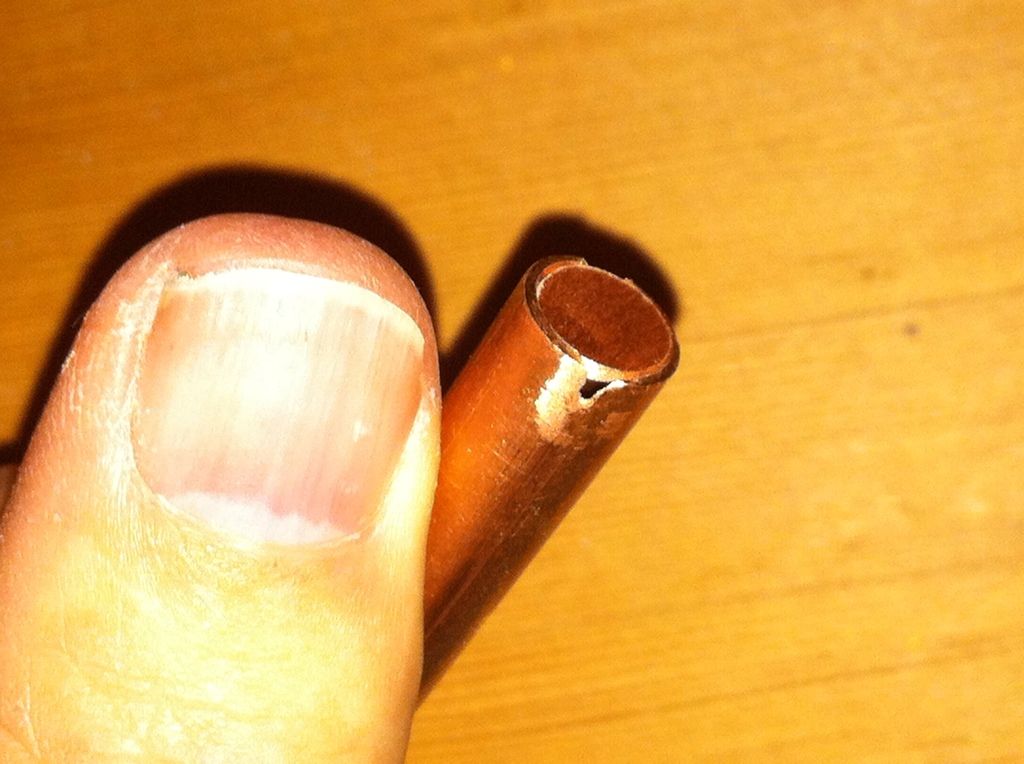
I used a dremel cut off wheel(thanks OL) in the drill press to cut the sleeve the correct length to fit into the bore.
The next thing on the list was some brazing which I haven’t done in awhile and slagged the first two parts I tried. Fortunately that union had two ends and effed up small parts are a small loss. In the end I got the brass male threads brazed to a brass plate that is the last fin and a small bit of copper brazed into a section of 5/16” copper tubing shown here prior to the first attempt.
The next pic is of the rough fins with the two part brass bit mentioned above at bottom left. I’m not sure yet if I’ll use these or go with a slightly thicker guage. I depends on how they stack up. 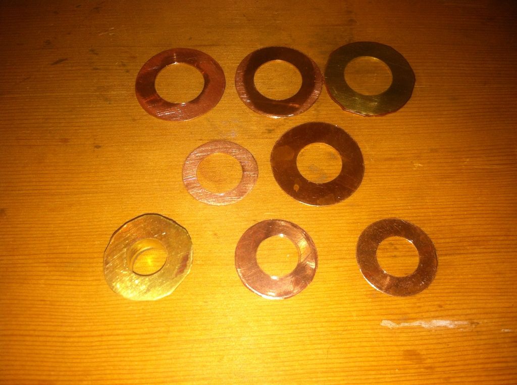
One thing I’d been having trouble doing is widening the center hole on smaller discs. If I put them in the vise with enough sticking out for the step drill to work they would either get mangled or squirm out IC the vise. Solution: sandwich it between two pre-drilled pieces, clamp one end in the vise and use my sheet metal vise grips on the other. With the pre-drilled hole it’s easy to center the disc. It stays flat and secure, and the step drill clears both clamps. Basically a miniature version of how I cut the rough discs from the sheet stock. 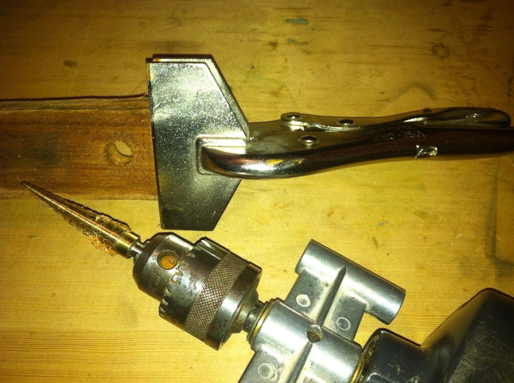

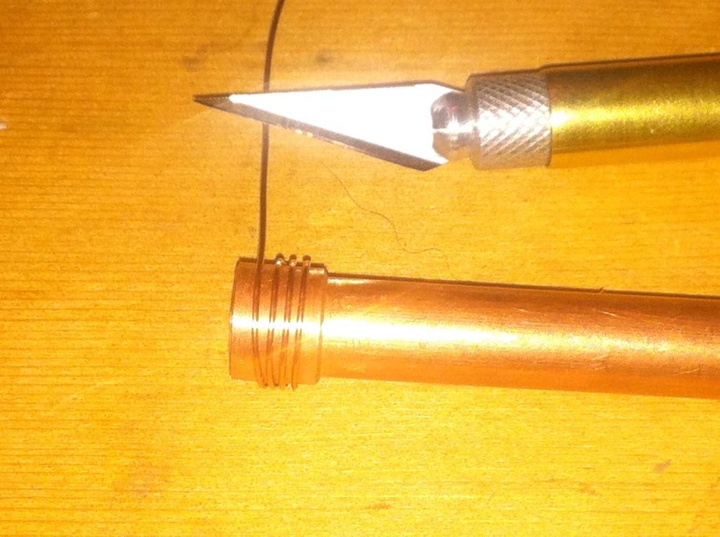
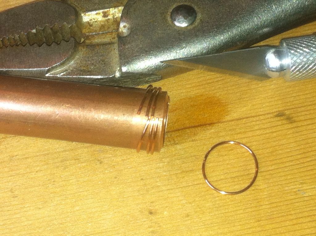
Lastly, I cut the wire spacers that go between the fins. This is .6 mm wire scavanged from multi conductor sprinkler control cable. After stopping the insulation, for each section of spacers I wrap the wire around tubing one size smaller so that it stays tight when I slip it around the correct piece and cut it.
That’s all for now. Soldering this thing is going to be a pain and I need to think on it so the next thing will be stacking the 10.5mm driver(now 10.2mm), sleeving the chips, and making the contact plate.
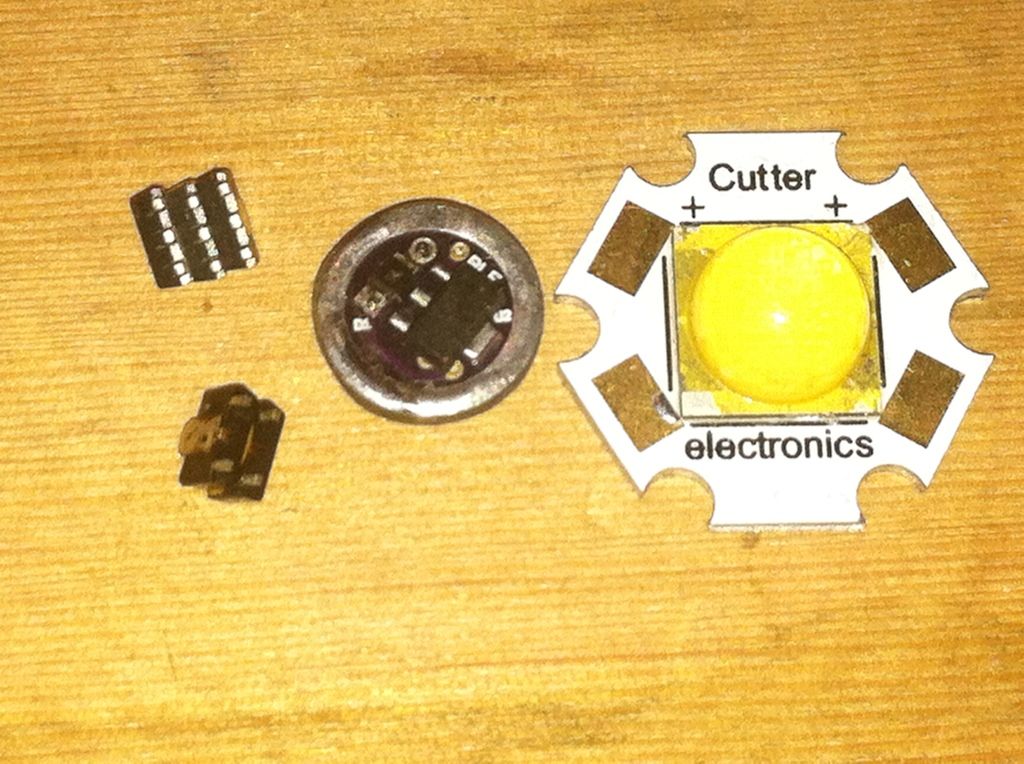
Here we have the 10.5 mm driver next to an mt-g2 and a double and triple stack of chips. I’ll be adding the triple stack here.
After sticking the stack in place with a dab of JB weld and allowing it to cure I soldered a short solid wire to pick up the led - pins and a longer one that goes through the pcb for led+. Some Teflon wire case is slipped over the solid wire and will be slid down tight to the pcb.
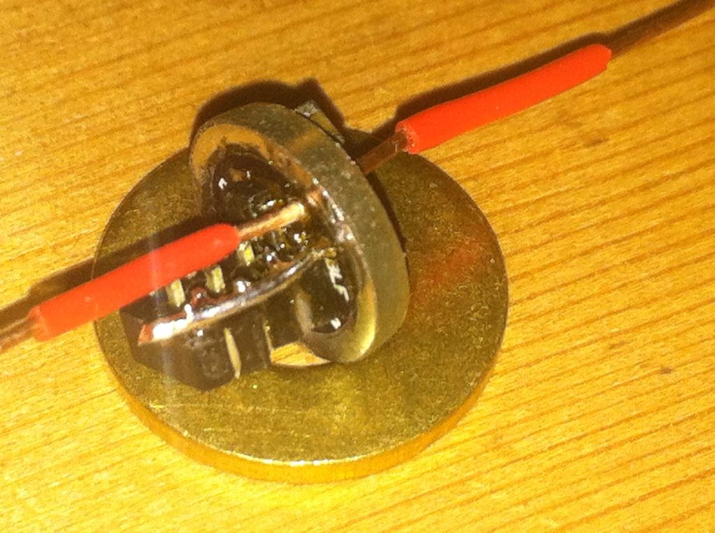
A big plus for the newer design driver board is through holes for both led+ and led- located at opposite ends of the board just like the mcpcb’s . This makes it possible to orient the chip stack either toward the battery or toward the led depending on where you have room. They also make a more secure connection for the wires. The board in this build is one of the beta boards without these features.
Next I’ll add the pwm wire and pot this stack in a nylon sleeve filled with Fujik. After that cures, I’ll add a tinned copper contact plate. An led-wire will make it ready to install.
A little side step. I brazed two more pieces and fitted them to the inner most copper part to which I added some more copper bits. On the left is the first brass fin with its threaded sleeve, next is the copper sleeve that will have the copper fins stacked on it, and then the inner post that gets the led on top. There are 4 pieces of brass in the first, two pieces of copper in the second, and 4 pieces of copper in the third.
And here’s how they fit together.
And,