The BLF comedy hour is proud to present, Dale the advanced learning curve electrician/comedian! Woohoo!
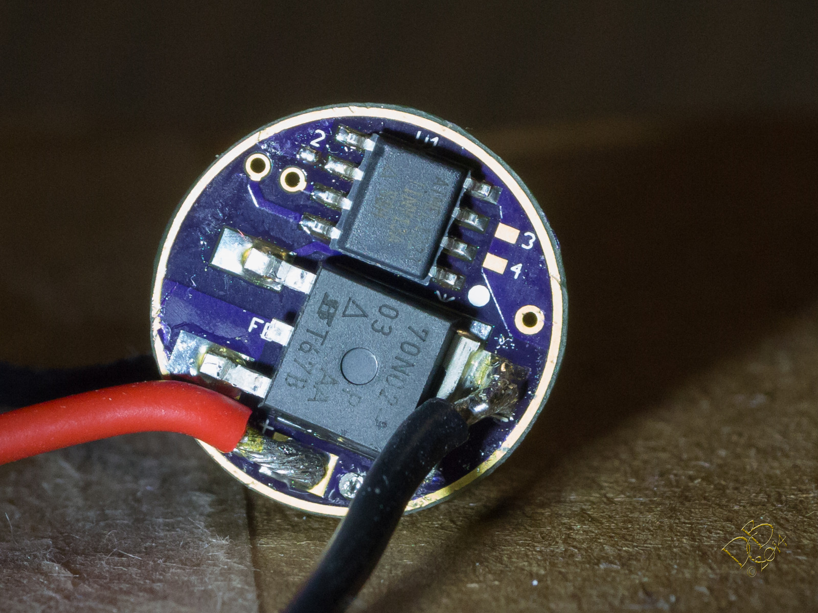
Ok, hi everybody. I’m Dale and I’m a flashaholic. A stupid one.  But hey, I’m also a SUCCESSFUL one! I pulled the ATiny from the new BLF FET 17mm DD board and reversed it. Worked out pretty well. I pulled a 200 Ohm resistor from my Zener kit and stood it up, held it in place with tweezers and soldered it under the previously prepared PWM leg of the FET. Simple enough, the Hakko work station makes all this pretty simple, even for a rank amateur like myself.
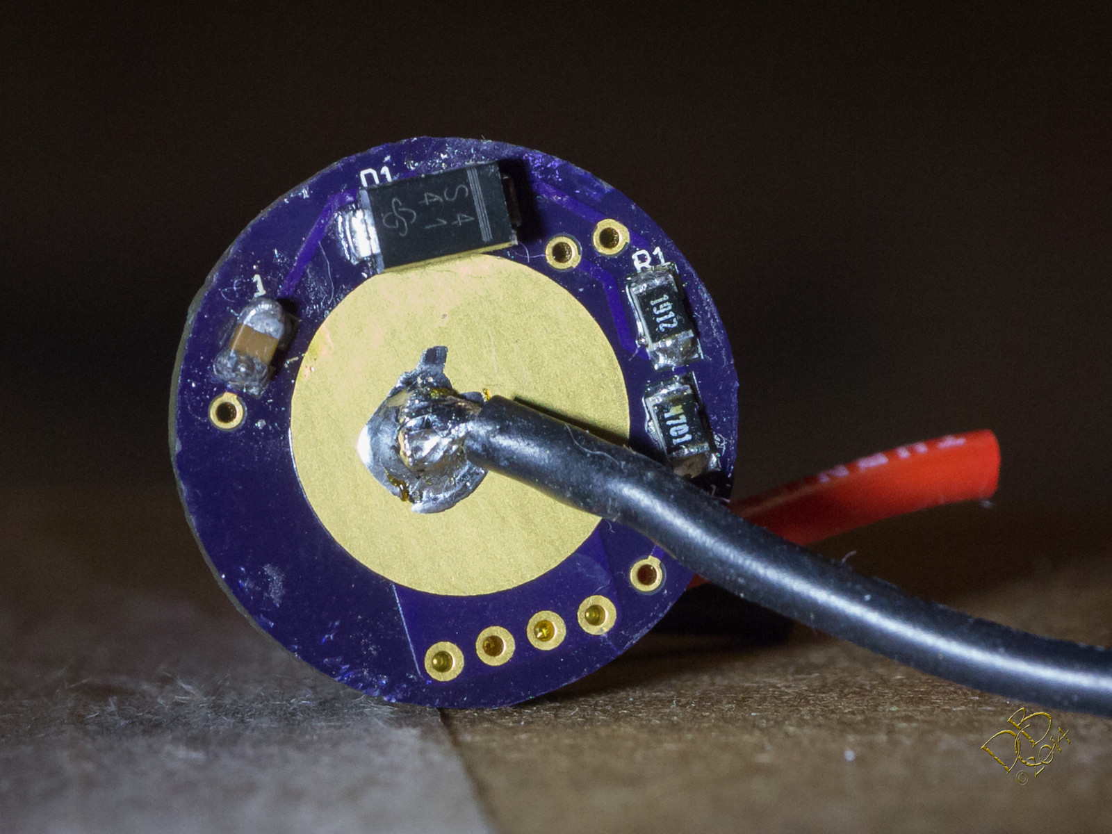
Now for the fun and games! I soldered the power leads to the test emitter and, with my DMM between, applied power. Smoke! Aiiiiieeee! (Hooked the incoming power leads to the emitter, outgoing to the cell) Oops!
Ok, situation corrected. wired up properly now it’s gonna work right? Uh, well, seems like the little hemostats are clamped on the positive pad and negative ring at the same time. Little sparks dance around the outer thin ground ring towards the positive pad and smoke curls up! Aaaaaiiiieeeee!
Ok, now, everythings clear, we’re good to go (man I’m glad I’m using a 18500 lap pull here and not a Sony C5)
4 levels from .05 to 4.40A with nice even positive switching. Whew! Finally!
Ok, yes, I’m embarassed. But hey, it could happen to anybody! And probably will happen to a few of YOU! So I wrote this to make sure y’all are dotting your i’s crossing your t’s and minding your p’s and q’s. 
(And I just found out that minding your p’s and q’s is in reference to tending your own Pint or Quart of Ale, so cheers!)
 )
)


