In MiniMo, change TCCR0A=0b00100001; to TCCR0A=0b00100011; for fast PWM (18kHz).
Note that a PWM value of 0 doesn't switch off in fast PWM mode.
In MiniMo, change TCCR0A=0b00100001; to TCCR0A=0b00100011; for fast PWM (18kHz).
Note that a PWM value of 0 doesn't switch off in fast PWM mode.
Thanks! I'll figure this out, eventually...
The LEDs don't turn off, but that's fast PWM when using 7135s, the FETs react differently at the very low end. But does the MCU shut down like it's supposed to? I haven't had time to experiment yet and check any of that, I guess measuring parasitic drain between phase correct & fast PWM versions (assuming the LEDs turn off) would answer that.
I do know that with the phase correct code it used to work with a value of 1, but after adding the gate resistor it no longer turns the FET on unless that minimum is raised to 2. With the same code the 7135s don't start working until 4 or 5.
If there was a performance difference between LFPAK & DPAK parts in this application the same as what there is between DPAK & 7135s, then we wouldn't be having this conversation and never would have bothered with designs using the DPAK parts...
I'm not opposed to changing anything ever for any reason, but I am opposed to changing things that end up only making it theoretically better on paper but don't show any difference in actual use. If they're both similar cost then that's a wash, the performance is similar since once you get down into the sub-10mOhms range there's just not much improvement to be had so that's basically a wash too, yes they are smaller so the board design gets easier so that's a real tangible benefit, and then the durability issue is a wash as well since neither design is highly stressed enough to show any vulnerability to failure.
The LFPAK devices require proper surface mount equipment to attach them to the board correctly… solder paste stencil, reflow oven, etc. And good luck getting them off if you need to…
Other than the small detail that it doesn’t fit on a 15mm board. I’m in no way suggesting we abandone using the dpak but that since it won’t work for all our needs that we look around for other options that will work in those instances.
FWIW, I finally discovered my error in the 17mm DD board. I don’t know electronics. I didn’t know the coding for resistors. Without that knowledge, a 1912 marking looked essentially just a little bit less than a 2000 marking. So I was using the wrong resistor by a long shot for the PWM gate. Fixing that, it works just fine.
For anyone following this that, like me, doesn’t know these things…the 4 digit identification has the 4th digit as a multiplier of 10. Such that 2000 is 200 to the zero power or simply 200. 1912 is 191 to the 10th power, or 19,100. Vastly different although the number itself looks so similar. And that, in a nutshell, is why messed up my second and third attempt at building this driver.
Pulled the 1912 resistor and put the proper 2000 resistor in place and it works just fine. ![]() (This is between the PWM leg of the FET and the pad to the MCU. This was added as a buffer to protect the high current on/off from killing the MCU)
(This is between the PWM leg of the FET and the pad to the MCU. This was added as a buffer to protect the high current on/off from killing the MCU)
2000 is still way too high, should be around 100-150 ohms on the one between MCU & gate.
The other one that goes between the gate & ground is there to provide a path for any leftover signal to drain away when the MCU turns off the PWM output, supposedly otherwise there can be a bit of charge trapped in the line and can keep the FET on when it shouldn't be.That one should be high, over 10,000, or else too much of the MCU's output can leak away and not go to the FET where it's needed.
Here's a cheat sheet for SMD resistor markings: http://www.hobby-hour.com/electronics/smdcalc.php
Believe it or not, when I found out I was using the wrong resistor I actually did research the identification codings for resistors. And realized I’ve seen all that before when modding my S2200 some time back. I can forget as easily as y’all blink your eyes. ![]() This is due to medical issues that have plagued me for going on 14 years. Such is life.
This is due to medical issues that have plagued me for going on 14 years. Such is life.
I’d never remember how to work a smart phone. Simple flip phone for me. You should see my trying to keep up with my Canon 1DsMkII. ![]()
The final success story…waiting now for the FandyFire HD2010 from the O-L group buy…
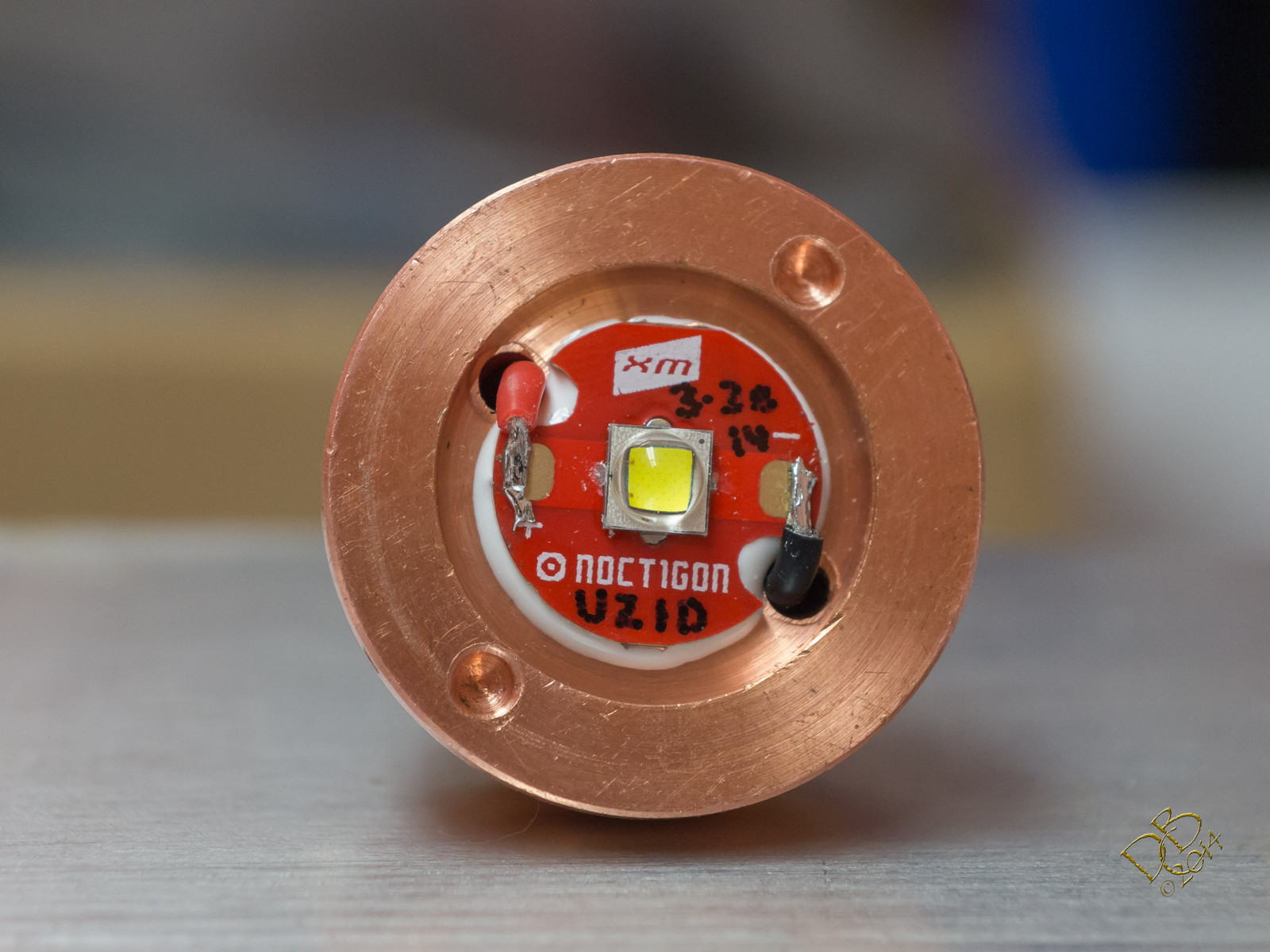

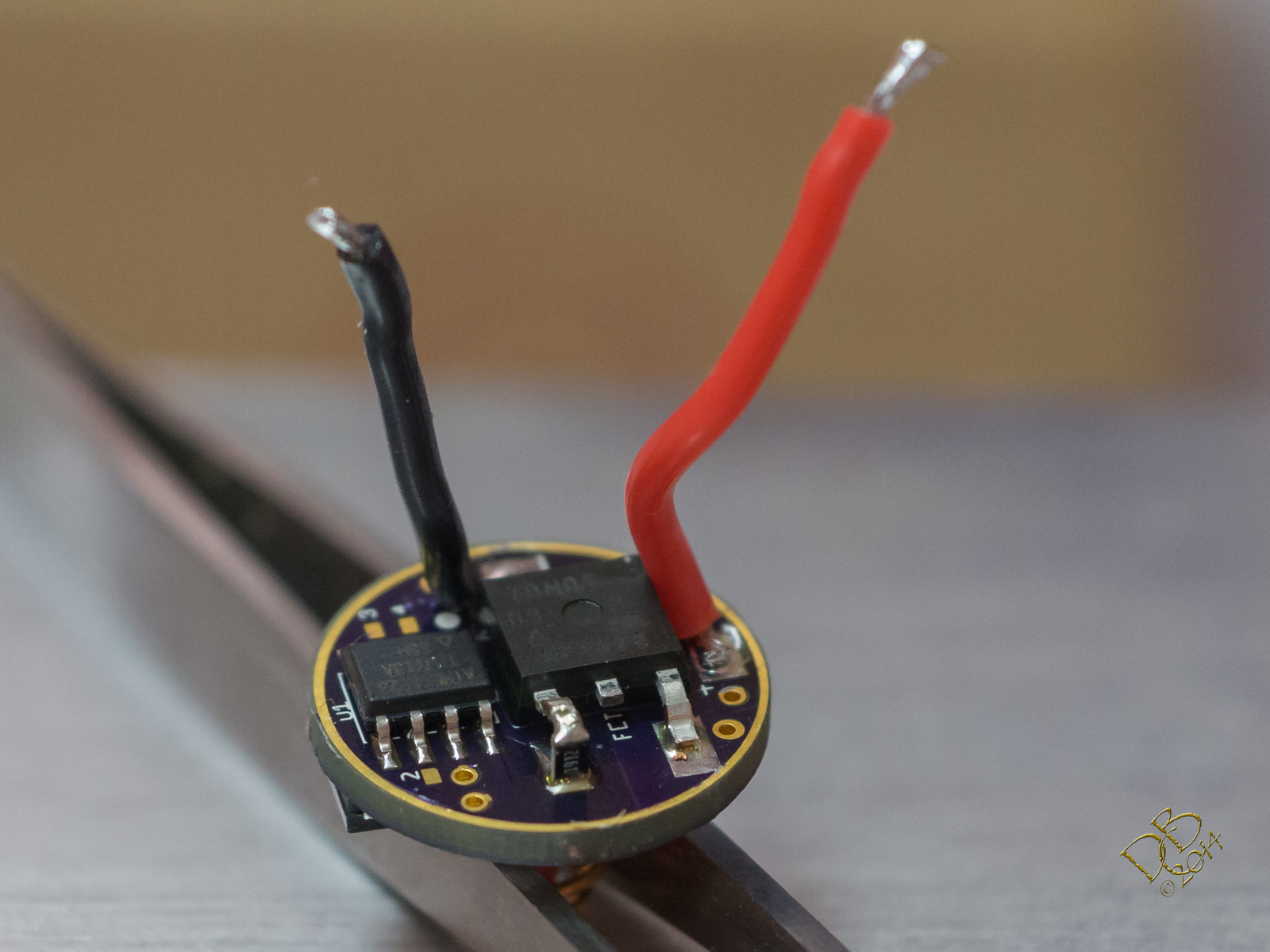
The above pic shows the wrong resistor, but it’s been swapped and is working perfectly now.
Nice tint, should have pretty good lumens output as the Efest 35A shows around 5.8A on Turbo. I’ll need to grab a couple of Sony 50A 26650’s and test em out here…
So that resistor helps with the mode selection using luxdrv?
and 5.8A…whoah!
Nice copper pill Dale. 
Are you leaving the dome on?
Well not quite… 1912 is 191 with 2 zeroes… 191 x 10 to the second power… 191 to the tenth power is a rather big number…
And just to make matters more confusing, 1% resistors (which you should be using in the battery monitor voltage divider) have a totally different marking code:
The resistor that’s standing up is to help soften the blow to the MCU when the big FET is switching on/off under PWM. I used that one erroneously and it severely affected the levels in my UI. As in it killed 2 of the 4 levels. The correct 200 ohm resistor lets everything work smoothly. Comfy has stated it could even be 150 ohm or 100.
Yeah, I don’t know why it’s only 5.8A…was looking for 6.6 or more. (Kinda like saying I’m disappointed my Cadillac Seville STS would only go 134mph when I was looking for 150, right? ![]() )
)
I have a few different heatsinks that I use for testing. One of them has a 1" x 4" solid copper bar press fitted into the aluminum finned portion. All of my emitters read low on that thing even direct drive until a few minutes pass then if I switch to new cells it will do it with some heat. I can take the same emitter and place it on one of my aluminum heatsinks and it reads much closer to what I see in my flashlights. Keeping these emitters cooler certainly seems to raise the vF significantly.
This copper pill for the HD2010 I believe weighs 73grams. The C8 from Buck has more than 8 ounces of copper under the copper star and it does 6.61A with an Efest 35A and the FET Qlite.
Nice job. How did you connect to ground?
I've added in-line and parallel resistors to the FET gate on the following boards, all marked as V2.0:
The SRK FET board will have to wait to be updated. Somehow the Eagle files for it have become corrupted and some of the layers have been deleted. It's a fair bit of work to get it back to the state it was and I just don't have time to build it back up this weekend sorry :(
- Matt
I’ll update the op and put a “do not order” on the SRK board.