Surely that tiny little FET takes less to drive than the big ones, does it need the gate & pulldown resistors?
No middle modes without the 100ohm on any cell. I don’t have the pull down 10k so can’t tell you. With 2 fets it seems fluky with higher drain cells(low modes jump up) and with 1 behavior is erratic(sometimes fine then a minute later not). Somewhere north of 1.5A is where the erratic behavior begins as it was consistently well mannered below that point. It seems to handle more than 2A well enough so maybe the 10k will fix the middle modes at the higher current? I would give much credence to the numbers posted in an absolute sense as there were a number of extra clips, cheesy meter wires, and solder connections involved. Reducing wire lengths and connections could easily change lots of values and operational details. This was just a run through to see what to try next using ready to hand parts. I’ll also need to play with the different stars as #4 was all off. I think a different chip might be in order for the blf15 as some of the cells I used are easily capable of topping 3A and none did more than 2.1A but I should try it again with better shorter wires before that choice is made. Some good testing done but plenty more to do.
It’s quite a bit brighter without the meter in the circuit so when Dale gets his hooked up maybe he can get some decent numbers. Anyone know what’s different about the firmware for star 4?
I used a new ATiny13A, flashed it with my FET hex file, all new components except for the diode, which I took off a Qlite board since it’s so small and the new ones I have are TRex’s by comparison.
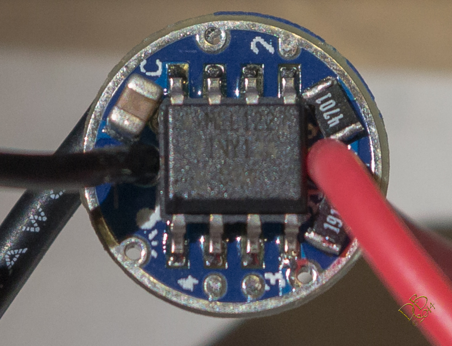
I used a solder mask to re-flow the MCU side of the board, it’s gorgeous, very neat and everything appears to be sitting just exactly where it fits best. Those 2 resistors are VERY close to the MCU pins but there just ain’t no room on this thin BLF Tiny board.
I did some of the best soldering I’ve ever done on the backside, did not put a resistor in the circuit as it’s such a small FET and the current will be so low I didn’t think it’d need it. Beautiful piece of work, I’m so proud! ![]()
But it doesn’t work.
Time for something you are good at. Pictures please. As you say, it’s tight on that board, especially on the mcu side. If you have the BLF 15 you could use the stencil for just the mcu and hand solder the rest. I wasn’t going to downsize until I had an upsize version working.
Edit- I’m not good at soldering, I’m just barely good enough.
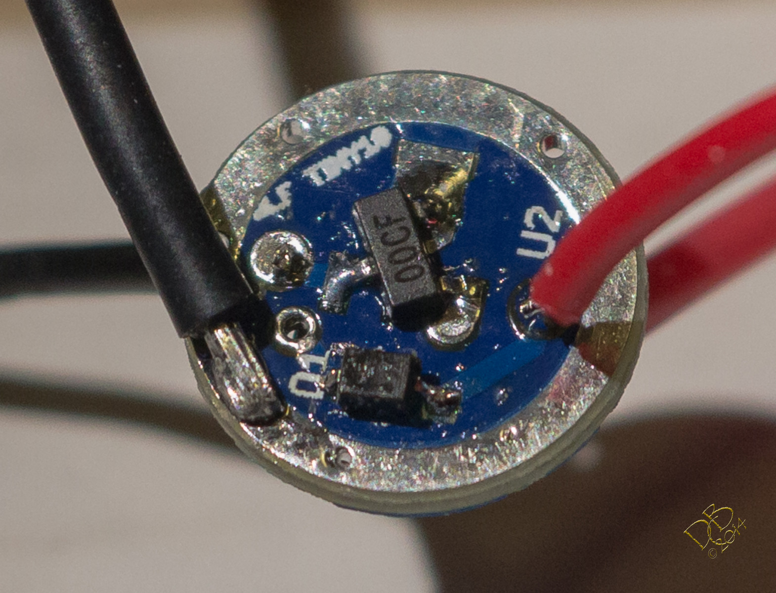
I might have the diode inverted, would that do it?
Sure looked like I was seeing the line to the left, but it appears here (blown up quite a bit) to be on the right. I will go pull that and reverse it, see how that goes.
I’m pretty good at getting things wrong these days! lol
Yep, diode is backwards. On the S4-marked parts the line goes to the output, the other side without the line goes to B+.
With that set up you should get something other than a buzz from smoke inhalation. It looks good but well have to take your word on the led connections. Can’t see anything there.
Sssh, we could gave kept him at it for hours.
Bad news is, I had the diode reversed. Good news?
I have 4 levels, .02, .29, 1.47 and 3.02 on an Efest IMR10440 sitting rested at 4.12V. ![]()
Oh, and I can barely see at the moment…
Awesome relfow job…very smooth!
Is that the current pull (.02, .29, 1.47 and 3.02) thru that Tiny10?
Is 3A safe for a 10440? Whoah…
Awesome. Well done. Care to do a failure analysis working your way up the current ladder?

You want me to feed it bigger bullets? Until it dies? Aw man that’s harsh! It’s such a pretty little thang!
The Efest IMR10440 delivers 3A routinely. I use em in my MBI HF’s that are direct drive to XM-L2’s. I’ve got almost a dozen of em. ![]() (cells, I mean, only 3 HF’s, of which I EDC 2 and the TP which also uses an IMR10440)
(cells, I mean, only 3 HF’s, of which I EDC 2 and the TP which also uses an IMR10440)
I, uh, well, I’ve got this 14500 high discharge cell that can probably fry the lil dude. I’ve got an AW IMR14500. Also an Int Outdoors protected 14500, and then I’ve got bigger fodder…
Ok, Ok, I’ll go run the 4.20V Efest IMR10440 through it, see what it says at full charge. BRB…
Well I gotta get offa my duff and start modding…I have 4 of those Mini C8’s now and a handful of other projects to do…dang
The 3.02A made me wonder..
I had only done output measurements on my LZZ-06 build sofar, I just did a current measurement with a full Efest 10440 battery held against the head: 3.45A on high 
I switched to 12 g solid wires on the meter and hit 4A with a keepower 18500
19.1K should be OK…
I took it up to 4.23A with an AW IMR14500, is that enough? .02, .32, 2.00, 4.23A And with subsequent runs, letting each mode sit in use for several seconds at least, it did about the same. Started getting a little lower as the cell pulled down but yeah. It’s up there. The IMR14500 was at rest at 4.08V.
Should I try the bad ass 14500? Or even bigger cells? I probably have something that will fry it, with Sony C4, C5, Efest 35A, Samsung 20R and 25R on hand.
A protected 18500 AW cell gave me .02, .26, 1.64, and 3.58A
The protected Intl Outdoor 14500 did .02, .29, 1.56, and 3.15A
Slightly off-topic: those Efest 10440 cells can do not stand endless torture, after 5 minutes at high on my little LZZ-06 BLFtiny12-FET build initially it looked like only the shrink-wrap had suffered from the heat, now a few days later brownish gooey came out pulverising the paper disc on top, it still works though...